A bit of a different one: $15 worth of downloads to the first person to tell me where – specifically – these rad warning signs are located.
This one should be easy to guess. However, I’m firing up the ol’ “contest machine” for this one. Anyone who can (and does) provide *verifiable* hard data on this (and I mean more than just the one reasonably well-known painting… I mean reports, diagrams, three-views, etc) gets a Perpetual APR Subscription… all previously published APRs plus all that the future will see.
UPDATE:
All the major bits and pieces are in place, but a fair amount of detailing is left (control surfaces, panel lines, landing gear, attachment pins, etc.). The modeler will be able to fix the wingtip fins in either up or down positions.
UPDATE: probably final, or close to it:
UPDATE: Final parts layout.
$25 worth of downloads from either APR or Drawings & Docs to whoever can *accurately* ID this vehicle. I’ll leave it up until someone nails it… or until I decide to end it. So there.. Context ended!
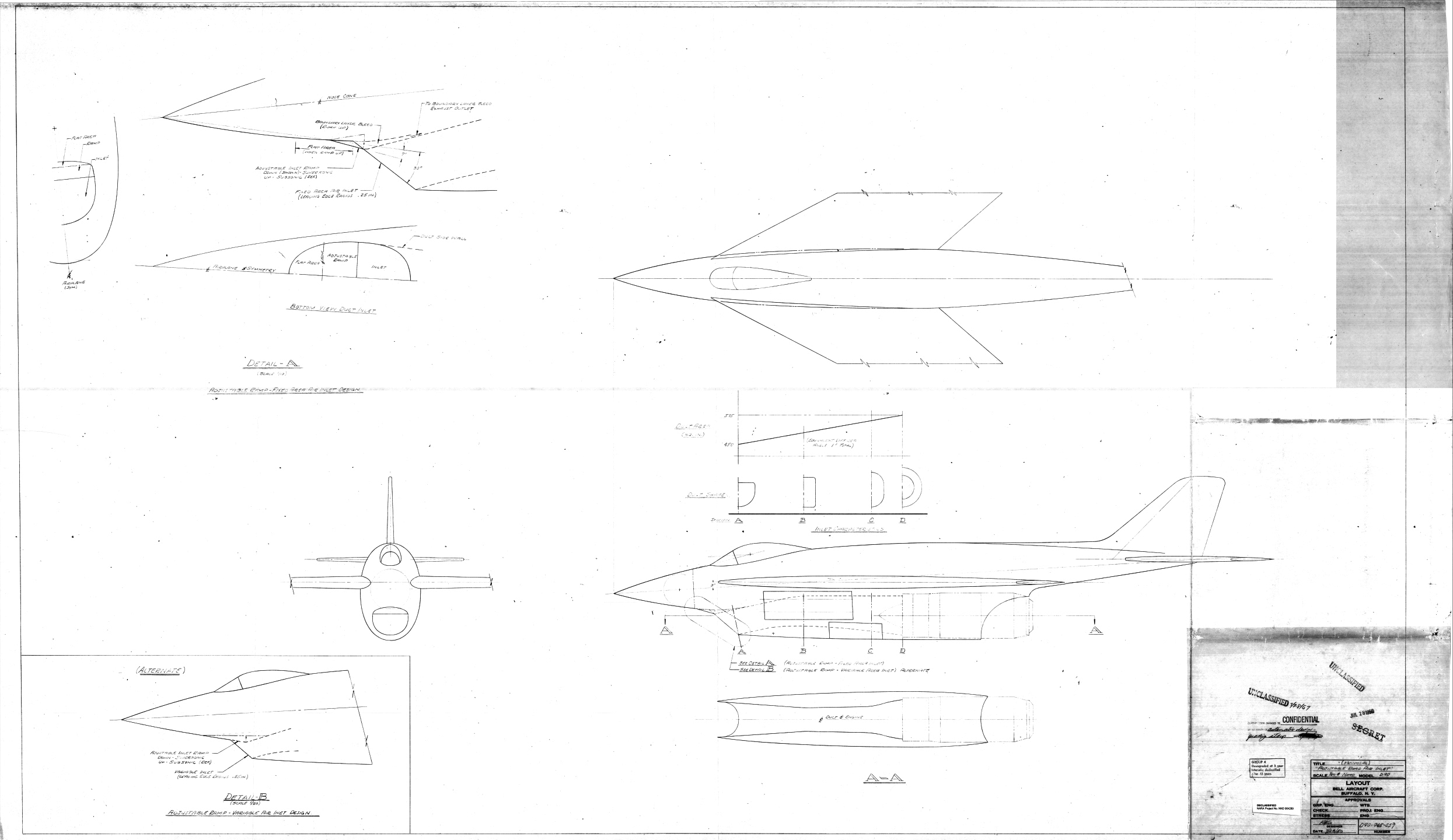
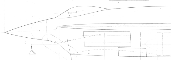
The answer to the last “ID this aircraft contest:” the Bell D90-945-057, a fixed-wing, supersonic derivative of the X-5 (itself a derivative of the wartime German Messerschmit P.1101). Known – at least to me – solely from a single large-format drawing held by the National Archives, this aircraft differed in important respects from the X-5. The fixed wing is the most obvious difference, but the pointed radome nose and the variable-ramp inlet certainly modernized the design considerably. Dates from 1950.

If you like this sort aerospace history and/or the other stuff I post, you can support the cause by Buying My Stuff, which includes aerospace drawings and documents, as well as the journal of unbuilt aircraft and spacecraft projects, Aerospace Projects Review. Or you could just Donate.
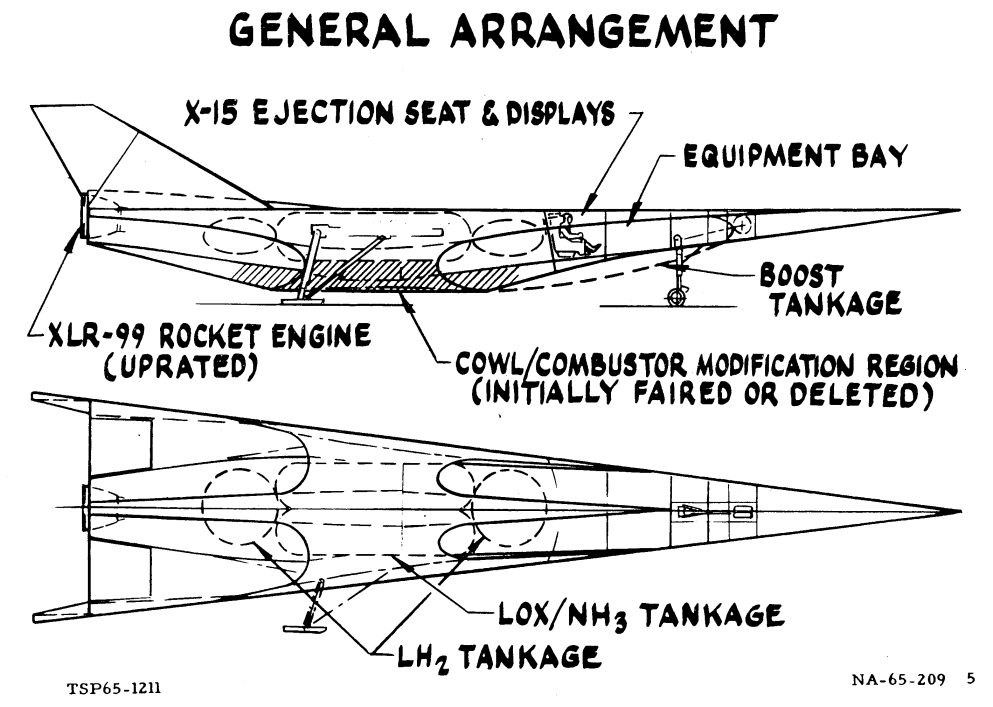
The sum total of my knowledge on this craft comes from this single illustration, found in the Boeing Historical Archives. It’s a 1965 drawing of a rocket/scramjet vehicle that made use of a few X-15 bits and pieces. Clearly it was designed to test high-speed airbreathing systems in a stepwise fashion… get to high speed on rocket power initially, with the scramjet engine either removed or faired over, and only later fire up the scramjet. To get up to speed, the rocket would use propellants that would be stored in tanks that served as fairings for the inlets. Presumably this vehicle would be carried to altitude by another aircraft. It looks big for B-52 carriage, but that was probably the intent.
The inlets appear to be “inward turning” style inlets, recently made popular in the “Falcon” program. The liquid hydrogen tanks appear to be pretty small, so it clearly was not designed to test long duration cruise of the scramjet.
Once again, I’m offering valuable and priceless rewards: $40 in APR and/or Drawings & Documents downloads for whoever can provide source material that gives a definitive ID on this, along with dimensions and, preferably, more illustrations.
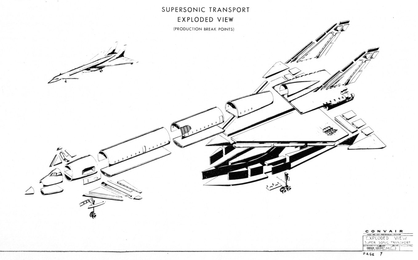
The answer to this contest: GD-Convair’s 1961 proposal to the FAA for a Mach-3 SST. Four Pratt & Whitney STF 102 H turbofans would power this airplane over a range of 3500 nautical miles, carrying 130 passengers. As with the similarly configured North American Aviation XB-70, the wingtips of the SST would fold down to generate compression lift at high speed. Span with the tips horizontal was to be 1379 inches. Convair suggested a market for 150 of these aircraft in the 1970-1975 timeframe. Cost was projected as $14.1 million per plane.
While the on-hand documentation for this plane is pretty lean, it appears that it has some family relationship to Convairs proposed B-58-derived SSTs (see here and here).


