Take a look at the listing of items to be auctioned off HERE on July 16 (direct link to 7 meg PDF file catalog). Some damned nifty stuff…
—
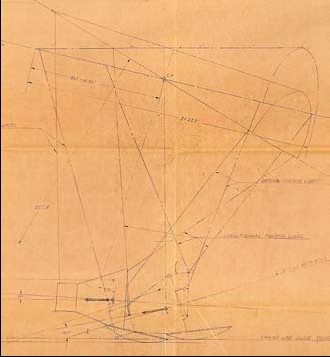
PARAGLIDER CONCEPTS.
Two large blueprints illustrating concepts for returning the Mercury
spacecraft to dry land using a triangular shaped airfoil:
1. “Study – Mercury Paraglider Controls,” blueprint, McDonnell Aircraft
Corporation, Saint Louis, MO, June 18, 1961, 108 by 36 inches, ¼ scale.
2. “Geometry Layout – Mercury Paraglider Controls,” blueprint, McDonnell
Aircraft Corporation, Saint Louis, MO, May 22, 1961, 81 by 36 inches, 1/20
scale.
Both blueprints signed by Max Faget as Mercury Designer. The paraglider
concept would save the expense of numerous armed services ships and
aircraft during an ocean landing. Various engineering problems prevented
paraglider use in time for the Mercury Program, but the concept became
part of the basis for popular “hang gliding” just a few years later.
Drawings include a side view showing an astronaut inside the Mercury
spacecraft with the heat shield deployed as a landing skid and shock
absorber. The paraglider airfoil is shown in various stages of stowage and
deployment.
$1,000 – 1,500
—
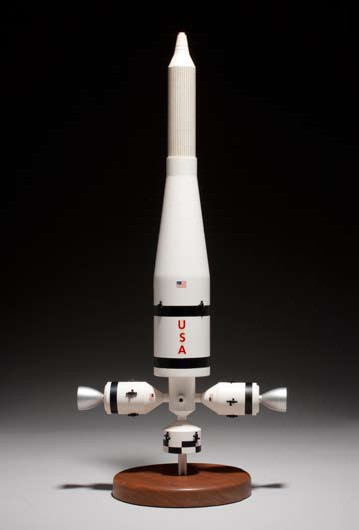
SATURN V MODEL.
Model of the Saturn V by the Marshall Space Flight Center (MSFC), plastic, composites, metal, and
wood, 48 inches tall when assembled, approximately 1/96 scale. Many parts identified with decals.
Housed in original MSFC wooden carrying case, 27 by 14 by 10 inches.
Each rocket stage is identified with large red decals near the center point of each stage. The first
stage (S-IC) is screw-mounted onto a wooden base. Each of the five F-1 rocket engines are clearly
visible at the base and painted in silver and red with touches of yellow and green. Four large
stabilization fins with fairings are at the base of the S-IC.
A fully detachable interstage ring separates the S-IC from the S-II stage and includes the eight ullage
rocket motors (these motors gave a brief burst forward to help “settle” the second stage liquid
propellants into the engine pumps during flight).
The S-II stage includes the five silver and red J-2 rocket engines and the slanted interstage assembly
with four small retro-rocket motors.
The smaller S-IVB/V or third stage fits into the slanted interstage. It has a single J-2 rocket engine and
dual auxiliary propulsion and ullage motors at the base. The Instrument Unit (IU) is attached.
An all-metal silver and yellow-colored Lunar Excursion Module fits inside the plastic Spacecraft-LM
Adapter (SLA) section which has a clear viewing port. The Ascent Stage and Descent Stage are
detachable from each other and the SLA section. The LEM’s landing legs can be deployed outward
from their folded positions. A removable white Command/Service Module (CSM) and Launch Escape
Tower (LES) are at the very top of the model. The Command Module can separate from the Service
Module. There are 7 mission thrusters on the CSM and 3 on the LEM.
A metal plaque on the 8½-inch square wood base reads: “George C. Marshall Space Fight Center,
Huntsville, Alabama, Graphics Engineering and Models Branch, SATURN V.” There is a 1-inch human
figure on the wood base for scale.
MSFC was the lead NASA center for the development of the vehicle which took Man to the moon.
The Apollo Saturn V rocket had a 100% success flight record. Nine Apollo crew traveled to the moon
powered by the F-1’s 1.5 million pound and J-2’s 225,000 pound thrust engines. Six two-man LEM
(later called LM) crews made landings there. In 1973, this vehicle’s first and second stages put the
Skylab space station into earth orbit. Included with the lot is a black and white photograph from
1966 of Dr. Faget with this Saturn V model in an MSC conference room area discussing aspects
of a lunar mission with visiting foreign dignitaries. This model is a superb icon of the technological
achievement made by the United States during the Space Race.
$10,000 – 15,000
Ten grand. Oh, why I aughtta…. grrrrr….
—
APOLLO 8 COMMAND MODULE CONTROL PANEL.
“Design Layout – Main Display Console, Command Module 103,”
blueprint, North American Aviation, Downey, CA, April 5, 1967 with two
revisions, the last dated March 12, 1968, approximately 79 by 11 inches,
scale not given.
Signed by a total of 15 Apollo astronauts, each giving their Apollo flight
numbers: Buzz Aldrin, Alan Bean, Gene Cernan, Gordon Cooper, Walt
Cunningham, Charles Duke, Richard Gordon, Fred Haise, James Lovell,
Edgar Mitchell, Wally Schirra, Rusty Schweickart, Dave Scott, Tom Stafford,
and Al Worden.
A blueprint illustrating the locations of the critical command and flight
controls of the spacecraft that took the first men to lunar orbit during
December 1968. Signed by a member or members of every Apollo flight
crew including Apollo 8 Command Module Pilot James Lovell.
The largest drawing is the Main Display Panel which was located in front
of the astronaut couches and has two large flight attitude indicators, the
re-entry monitor, caution and warning panel, 28 meters, and over 100
individual switches.
$2,500 – 3,500
—

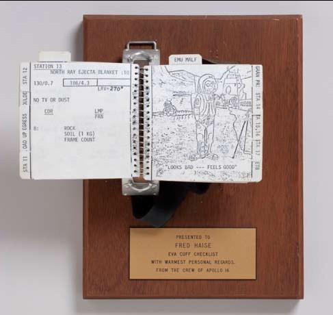
FLOWN APOLLO 16 EVA CUFF CHECKLIST.
ASTRONAUT CHARLES DUKE’S SPACE SUIT CUFF CHECKLIST.
Cuff checklist, comprising 29 thin plastic printed leaves, spiral-bound and
attached to a 7-inch curved metal wrist band (“P/N SEB 33100302-302,
S/N 1025”). Each leaf 3½ inches square and with a reference tab on the
fore-edge, 2 also with tabs on the top-edge (for immediate access to EVA
3 activities and EMU malfunction trouble-shooting steps). The wrist band
has an 18-inch Velcro strap (“P/N SEB 12100030-201, S/N 1087 ASSY”).
The whole assembly mounted on a wooden base with plaque reading:
“Presented to Fred Haise, EVA cuff checklist, with warmest personal
regards from the crew of Apollo 16.”
The cuff checklist used by Lunar Module Pilot Charles Duke, Jr., during the
second and third lunar surface explorations of the Apollo 16 mission. It was
exposed directly to the lunar environment for over 12 hours during those
exploration periods, and continued the tradition of bringing a smile to the
astronauts’ faces while providing back-up plans for the first lunar “Grand
Prix.”
Apollo 16, flown in April 1972, was the fifth lunar landing mission, and
targeted the Descartes region of the moon, some 250 miles southwest of
the Apollo 11 Tranquility Base site. This area was the first true highland
region of the moon visited by Apollo astronauts and has brightly rayed
craters with structural features similar to volcanic areas on the earth.
Astronauts John Young and Charles Duke were scheduled to spend 73
hours at the Descartes landing site and to perform three EVAs. Just prior to
the Lunar Module’s descent from lunar orbit down to the landing site, the
Command/Service Module developed problems associated with its large
rocket engine, known as the Service Propulsion System (SPS). Since the
SPS was the only means to leave lunar orbit and return to Earth, the lunar
landing was delayed about six hours until the situation was deemed safe
to continue the planned mission. This curtailed the overall lunar stay to 71
hours.
Apollo mission planners were well aware of the importance of making
every minute productive while astronauts explored the lunar surface.
Neil Armstrong and Buzz Aldrin had a single “page” made of space suit
material and placed directly on the left arms of their space suits, listing their
surface activities. This was adequate for a single 2 ½ hour EVA, but the
flights starting with Apollo 12 planned for at least 2 separate EVAs lasting
at least 4 hours each. With the lunar rover flights of Apollos 15, 16, and
17, the exploration times were extended to 7 hours and 3 EVAs. In order
to make certain the lunar explorers did not overlook planned tasks, spiralbound
cuff checklists were created to provide a detailed script of each
task or activity. This put all the complex procedural steps of an EVA at the
astronaut’s fingertips. Young and Duke each had two individual cuff check
lists for this mission, one for EVA 1 with the ALSEP deployment, and the
present checklist for EVAs 2 and 3, which focuses on the true exploration
and sample-gathering objectives.
The cover of the present checklist features a black and white Apollo 16
crew emblem. The verso has the printed signatures of those who prepared
and approved this checklist, including Charles Duke, and the title “Apollo
16 EVA 2 & 3, Lunar Surface Cuff Checklist LMP.” A date of 3/20/72 and
LMP ascending page numbers are printed in the inner margin. Eleven and
a half leaves are devoted to tasks associated with EVA 2. Two leaves cover
steps associated with space suit connections prior to venting the LM’s cabin
atmosphere. That venting allowed the front hatch to open and the next
steps of climbing down to the lunar surface. Once the preparations were
completed around the LM and the lunar rover loaded, the crew found
a special drawing on the next leaf. It features a drooling space-suited
astronaut melting away in the arms of a buxom nude woman. The astronaut
says: “Happy Birthday Whatever Your Name Is.” This gag illustration
continues the tradition started on Apollo 12 with the cuff checklists that
had small images of Playboy pinups and Snoopy cartoons. These gags were
master-minded by devious back-up and support crew members.
The next six leaves list the activities for lunar sites 4 through 10. These
were called “Station Stops” and the checklist pages have plans of
craters, placement positions for the rover, and suggested areas to take
panoramic photography. Tasks listed include taking core samples, scientific
measurements, and notes for geologic observations. Station 4 was located
about one mile south of the LM on the slopes of Stone Mountain, and
marked the highest point reached during their explorations. Stations 5 and
6 were located along craters at the base of Stone Mountain, with material
that landed after the creation of nearby South Ray Crater. Station 7 was
dropped as a stop to continue on to Stations 8 and 9, that were either on
or very close to a bright ray from South Ray Crater. Station 10 was very
close to the LM and was followed by activities to stow collection samples.
This is listed on three additional pages (one and a half leaves).
EVA 3 begins with a full 2-page spread reviewing procedures and objectives
for sampling lunar rocks and boulders. Three more leaves have the steps
similar to the beginning of EVA 2. Six and a half leaves describe tasks
planned for Stations 11 through 17. Due to time constraints related to the
delayed landing, Young and Duke only explored the areas at Stations 11
and 13. Station 11 was at the very edge of North Ray Crater and was the
greatest distance from the Lunar Module. At a boulder the crew called
“House Rock” (due to its large size), Young took several pictures while
Duke took samples. In those pictures, this checklist opened to the Station
11 pages can clearly be seen on Duke’s left arm (a photolithograph is
included in the lot). The crew then continued back toward the LM and
stopped at Station 13 where they found a spot to gather lunar soil under
a large boulder that was “permanently shadowed.” This meant that soil
was not exposed to millions of years of solar radiation after the boulder fell
there from a nearby impact. A full page after the last task for Station 13
features the second gag cartoon. It shows Young blocking the view of the
TV camera by hand with a “relieving” look on this face. A caption reads:
“Looks Bad, Feels Good.” Two additional pages cover steps to close out this
final EVA.
As a contingency, a 2-page spread was included at the end of EVA 3
activities listing steps with a diagram for the first lunar “Grand Prix.” In
case this test was unable to be done in the original plan for EVA 1, a backup
period was set within the EVA 3 timeline. The “Grand Prix” involved
Young driving the lunar rover at the highest speeds possible with Duke
recording the sprint with a 16mm motion picture camera. Part of the
objective was to have a visual record of how the rover bounced around and
the amount of lunar dust kicked up by the wheels. This was actually done
during EVA 1, thus not required at the end of EVA 3.
The final six leaves list trouble-shooting steps for eleven possible EMU
malfunctions such as activation problems or loss of voice communications.
Accompanied by a Typed Letter Signed by Back-up Commander Fred W.
Haise, which reads in part: “This Apollo 16 ‘Cuff Checklist’ was presented
to me by the crew of Apollo 16 as a thank-you for the role I played as the
back-up Commander for this flight. Charlie Duke wore this checklist outside
on the lunar surface during the last two exploration periods of Apollo 16,
known as EVA 2 and EVA 3. It was exposed directly to the airless lunar
environment for over 12 hours and spent approximately 71 total hours on
the moon during April 20 to 23, 1972.”
$200,000 – 300,000
BOGGLE
—
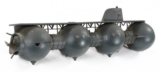
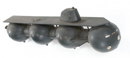
EARLY SPACE STATION MODEL.
Model of a prototype Space Station, composites, metal and decals, 20
inches tall. Comprises an Attitude Control Module at the base with four
sets of “quad” attitude control thrusters. This module is attached to a
Docking Port Assembly with two CSM’s attached (up to four CSM’s could
dock at one time). A Saturn-type upper stage is attached to the docking
area and tapers to a point. All sections removable and mounted to a
circular wooden base.
$3,000 – 5,000
—
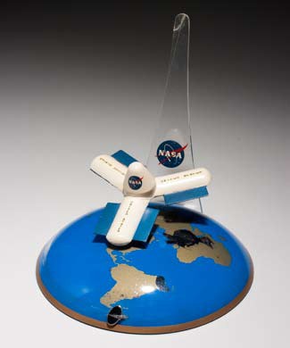
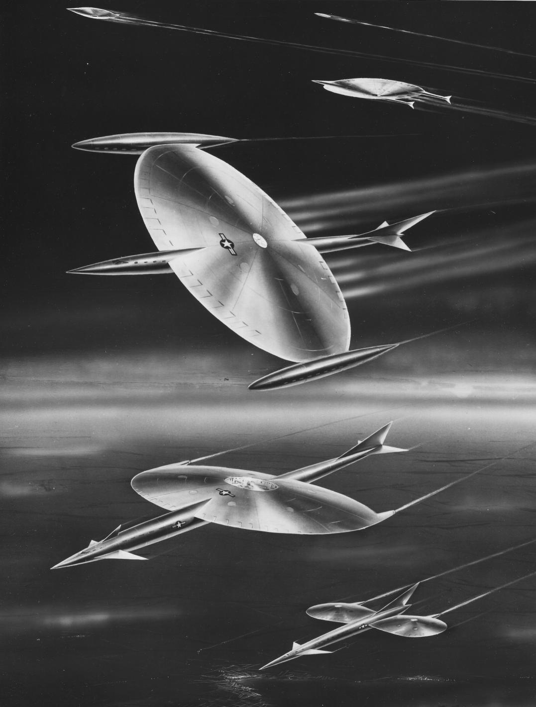
LOCKHEED SPACE STATION MODEL.
Model of a Lockheed “Y”-design Earth-orbiting space station, painted
wood and plastic, 7 inches tall with a 5-inch diameter base. Comprises
a circular base representing the Earth and a 6-inch clear plastic “vector
tower” from which the space station model is suspended. A magnet in
the base holds the station ‘above’ the surface of the Earth. A small metal
Lockheed logo is on the base. The NASA emblem is on the vector tower
and the station.
This station was designed circa 1964. It would rotate in Earth’s orbit to
provide artificial gravity for the crew. Gravity would increase as crew
members moved down the levels inside each of the “arms.” The central
hub provided a pressurized area for zero-G experiments.
$1,000 – 1,500
—

APOLLO SOYUZ MODEL.
Model of the American Apollo CSM and Russian Soyuz, by Pacific
Miniatures of Alhambra, CA, wood and painted metal, 17 inches long
assembled. The two vehicles are connected by a black Docking Module
(DM) which provided a functional docking port for each spacecraft. The
entire model is mounted above a 7-inch oval wood base with a plaque
reading: “Apollo-Soyuz Test Project, Scale 1/50, Space Division, Rockwell
International.”
$3,000 – 5,000
—

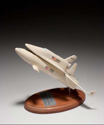
ROCKWELL-GENERAL DYNAMICS SPACE SHUTTLES MODEL.
A large and impressive model set by Rockwell and General Dynamics,
composite material, metal, and wood. Features a pair of shuttle orbiters
each designed to use a common booster vehicle. The booster, 15 inches
tall, is mounted vertically at the center rear of a wood display stand. It has
12 silver rocket engines at the rear, a large V-tail stabilizer, and detailed
paint and decal markings. The straight-wing orbiter, 11 inches long,
and the delta-wing orbiter, 10 ½ inches long, each have two rear rocket
engines. Both have detailed paint and decal markings. Tthe landing gear of
each is permanently mounted to the base, though each can alternatively
be lifted from metal pegs on the landing gear and mounted to the booster
vehicle. A large metal plaque on base reads: “Space Shuttle – North
American Rockwell Space Division – General Dynamics Convair Division.”
Smaller plaques alongside read: “Limited Cross Range Orbiter,” “Maximum
Cross Range Orbiter.”
The designs for these vehicles were released by these contractors during
November 1970, in response to NASA’s Phase B Integral Launch and
Re-entry Vehicle competition. Included is a NASA photograph of Dr.
Maxime Faget at his JSC office area holding the booster component of the
present model. Both orbiters and the large wood base can be seen on a
table in the background.
$7,000 – 9,000
—
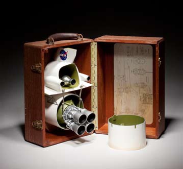
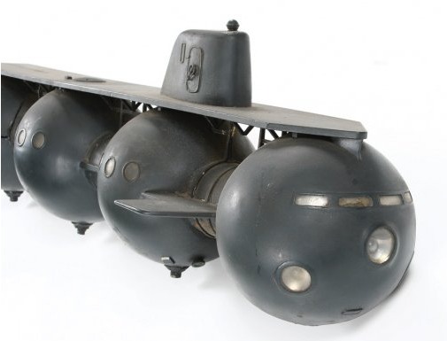
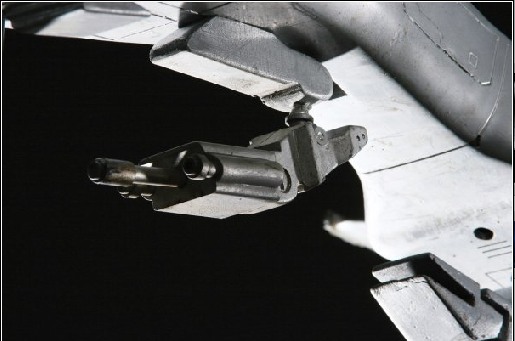
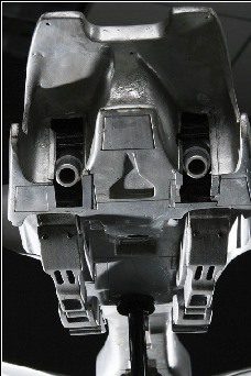
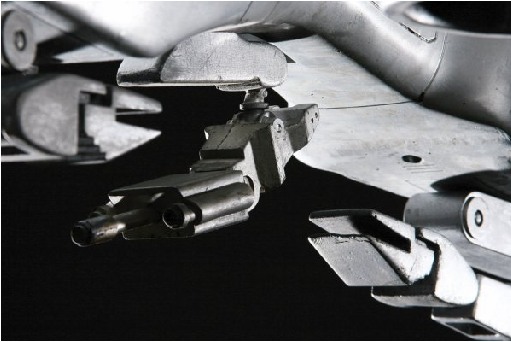
SPACE SHUTTLE REUSABLE ENGINES PROTOTYPE.
Prototype model displaying reusable engines for the Space Shuttle, made
by Technical Services Division, MSC, Houston, TX, plastic, metal and
decals, comprising a 9 inch wide aft end of an orbiter alongside a 5½ inch
diameter external tank, mounted onto a 13 by 9 inch wood base. With
original 15 by 9 by 10 inch wood carrying case.
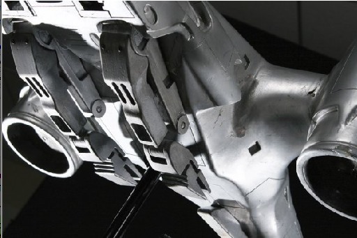
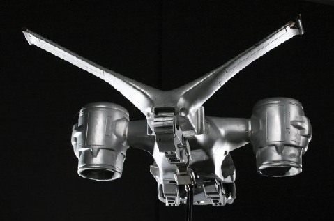
There are four modified Apollo J-2 rocket engines attached to the base of
the external tank. Hinged arms allow these four engines to be moved and
mated to the orbiter section. There is a removable interstage ring attached
to the external tank. The inside lid of the carrying case has a series of scale
drawings titled: “Orbiter Configuration 040B and External Tanks. MSC-SDD
– Oct. 12, 1971.” A side view shows how the orbiter and external tank are
located above a booster vehicle. Additional side and aft drawings show the
translation of the rocket engines from the external tank to the orbiter. The
case lid bears a NASA meatball logo.
A new propulsion concept by Maxime Faget. This design allowed for
the engines to be reused after removal from the external tank or to be
jettisoned reducing weight during an ascent abort. The design was never
implemented for a shuttle flight vehicle, but it was patented in December
1975 by Dr. Faget, W. Petynia, and W. Taub. A copy of this patent is
included with the model.
$5,000 – 7,000
—
SPACE SHUTTLE CONCEPT.
Model of a concept Space Shuttle, designed by McDonnell Douglas, plastic,
metal and decals. Comprises a booster, 10 inches long, and a delta-winged
orbiter, 6 inches long. The orbiter is separable from the booster section.
The two parts slot onto pins above a wooden base with a plaque reading:
“McDonnell Douglas Space Shuttle, McDonnell Douglas Astronautics
Company.”
This particular concept was one of the many industry designs responding
to a 1970 NASA Phase B competition for an integrated launch and re-entry
vehicle, commonly called a space shuttle. The entire vehicle would be
launched vertically with the larger booster section returning to a runway
landing for reuse. The orbiter section would continue into earth orbit
and perform a gliding re-entry and runway landing once the mission was
completed. Presented to Dr. Faget during the early 1970’s.
$2,000 – 3,000
—
—
I can’t afford any of this stuff.

Now, if any kind reader of the Unwanted Blog wants to procure these items and donate them to me… why, I’d *swear* to make a good faith effort to not be rude to you for, oh, at least a week.


