Sep 052010
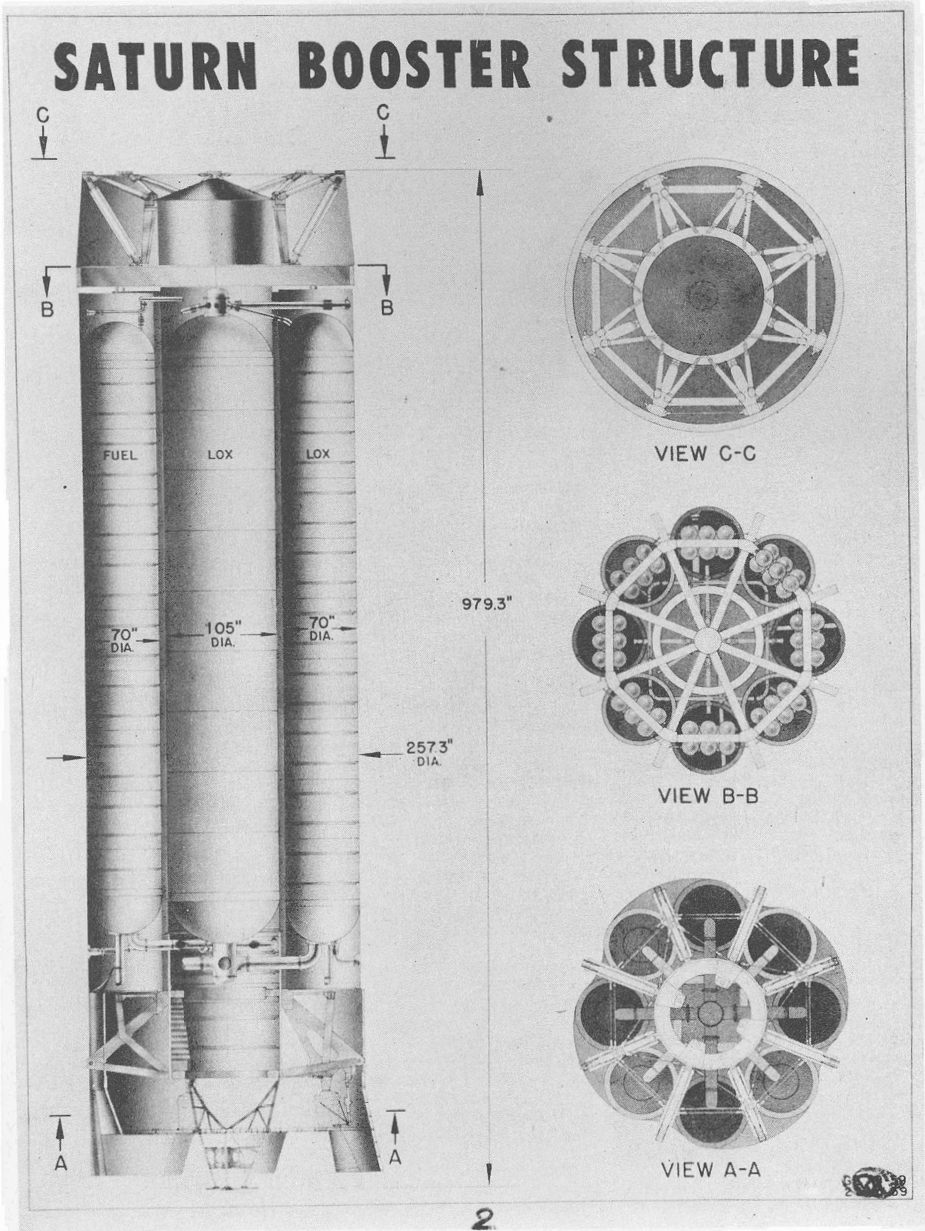
US Army Ballistic Missile Agency artwork from 1959 depicting the then-current configuration of the Saturn first stage. While generally much like the Saturn I that actually flew, note differences such as the large parachute pack in the nose for booster recovery.
2 Responses to “Saturn Booster Structure”
Sorry, the comment form is closed at this time.
Whoever came up with the concept of using the eight lengthened Redstone tanks around the lengthened Jupiter tank showed real imagination.
But one thing has me baffled here…the B-B section seems to show helium tanks for pressurization of the propellant tanks. Was that to drive the propellant into the H-1 engines (which had turbopumps), or to fill the empty tank space above the propellants as they were consumed, to prevent the tank structure from collapsing.
To me, just putting vents on the fuel tanks to let in exterior air, like was done on the V-2 alcohol tank, seems like a simpler solution.
The five Lox tanks don’t really need any sort of system like this, as Lox boil-off will keep the pressurized anyway during ascent.
Let me guess, the ‘chutes came off after NASA was born and took over the design.
You need to link this to the H-1 engine dunking in seawater and reuse work you covered a few months ago.