A few decades before the “X-Wing” configuration gained a measure of popularity, Hughes Tool Company made a detailed study of a somewhat similar concept, the “rotor/wing.” This was a three-bladed helicopter rotor attached to a large central lifting surface, either a circular disk or a triangular structure. The rotor was not turned the conventional way with a turbine engine turning a drive shaft, but instead the engine exhaust was ducted through the center and then out to nozzles at the tips of the rotors. Jet thrust would spin the rotors without transmitting torque to the rest of the vehicles; as a consequence only a small tail rotor would be needed, just powerful enough to orient the craft at low airspeeds.
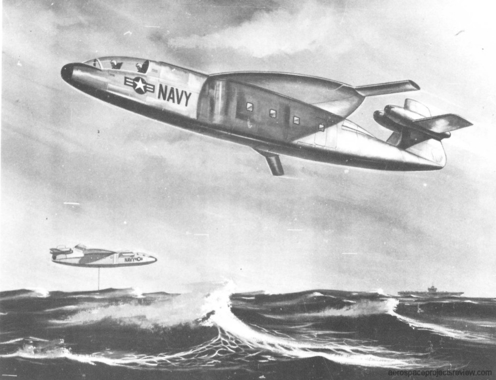
A few configurations were produced, most of which looking much the same. Probably the most well known configuration was shown in US VTOL Projects 01. Shown below is a lesser-known configuration designed for anti-submarine use. Normally the configurations included the turbojet engines within the upper fuselage, close to the hub of the rotor, but this one rather bizarrely put the engines on the tail. No obvious means of ducting the exhaust to the rotor is evident, so presumably a third (or even fourth) engine was tucked into the fuselage somewhere.