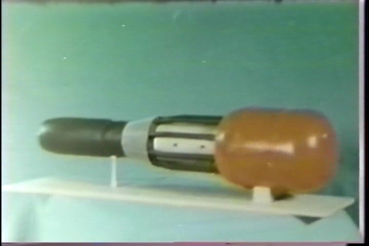
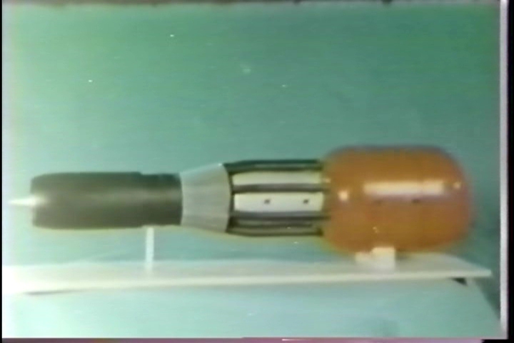
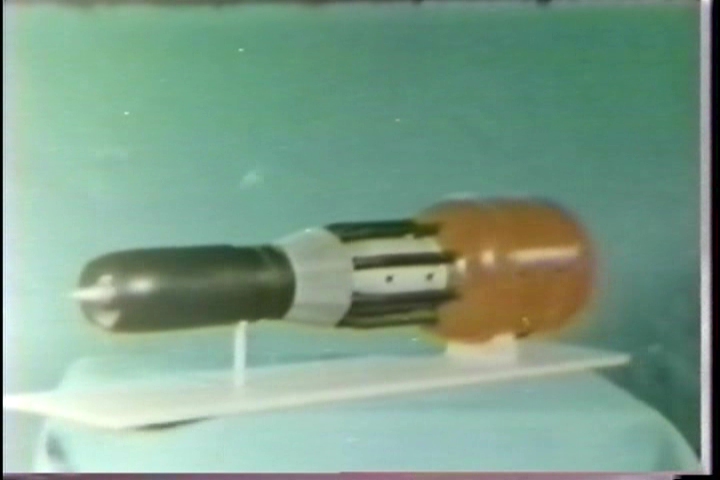
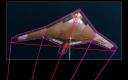
A single photo has been revealed showing Lockheed’s “Senior Peg” concept. Senior Peg was the codename given to Lockheed’s competitor in the Advanced Technology Bomber program, which was won by Northrop, producing the B-2 Stealth Bomber. Lockheeds design was vaguely similar, but differed in numerous areas, including having small tails, and, apparently, F-117-style facetting on at least the wings and F-117-style inlet “grates.” The Northrop concept, with was all smooth flowing contours, turned out to be better at radar stealth, so the Senior Peg vanished.
The single photo shows a half-scale model of the Senior Peg on a tall pole at a radar test range. No drawings have been released of the Senior Peg. So if a guy, a regular Joe, wanted to make a model of the design, he’d need to cook up his own diagrams, using only this one photo (kindly provided by Tony Landis):
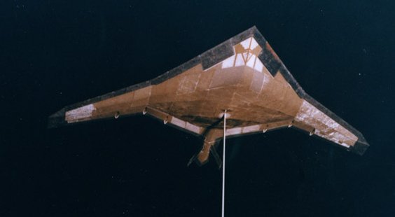
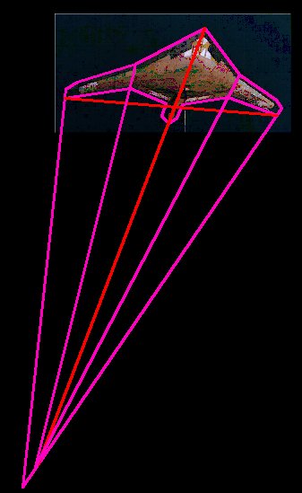
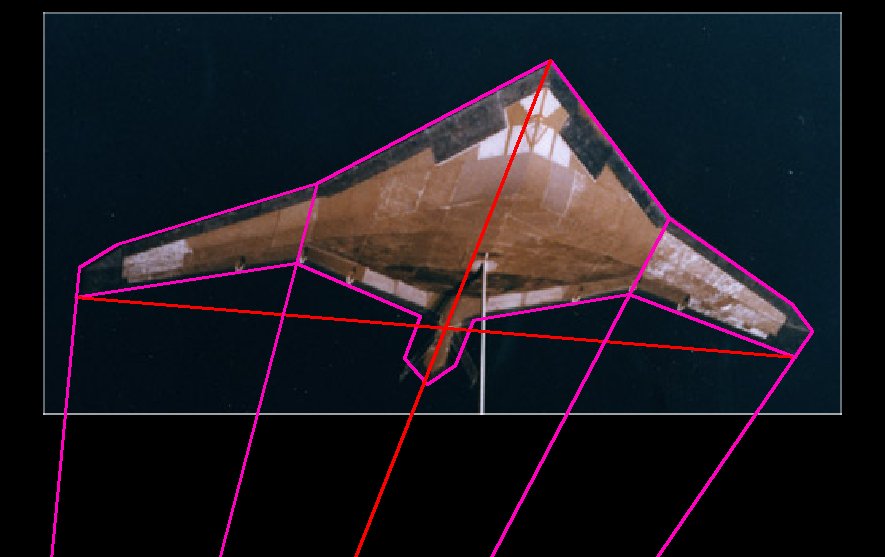
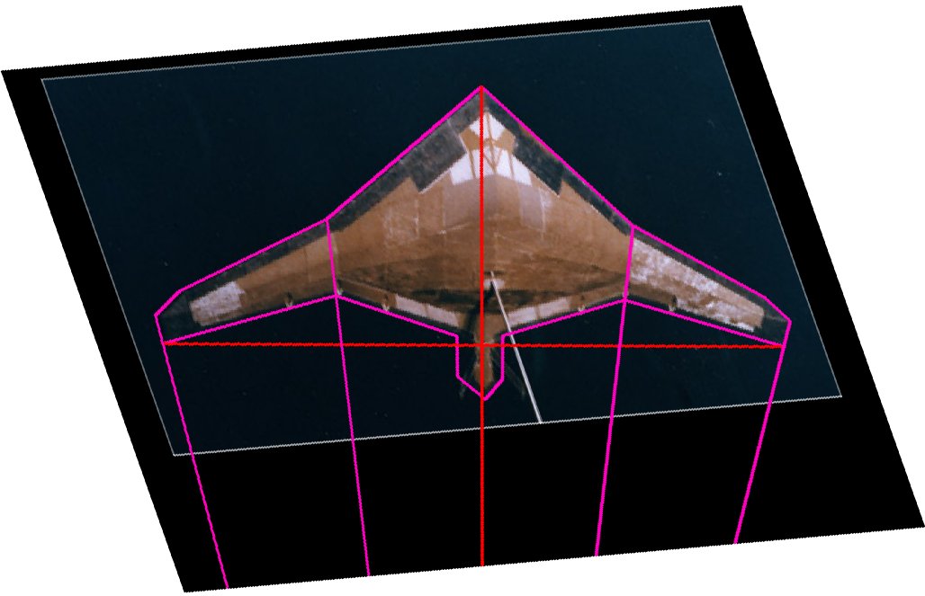
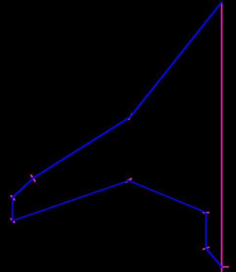
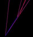
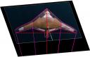
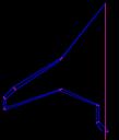
Converting this photo into a reasonably accurate set of drawings is relatively straightforward. The design appears to be pretty planar… the wing, like that of the B-2, has little to no dihedral. Thus the lines that make up the planform – leading edges, trailing edges, wingtips, etc – are all co-planar. First step: import the photo into a CAD program. Then trace the outline, and add in perspective lines:
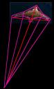
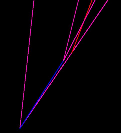
Looking at the perspective lines, two things are clear:
1) The vanishing points for the lines from the wingtips are not the same as the vanishing points for the wing root lines
2) But they’re close.
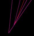
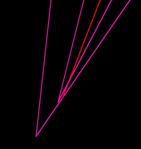
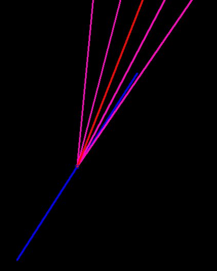
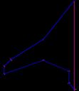
Since they’re close, but not identical, simply draw a line connecting the two vanishing points, then adjust the vanishing points to the centerpoint of that line. This averages them out.
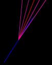
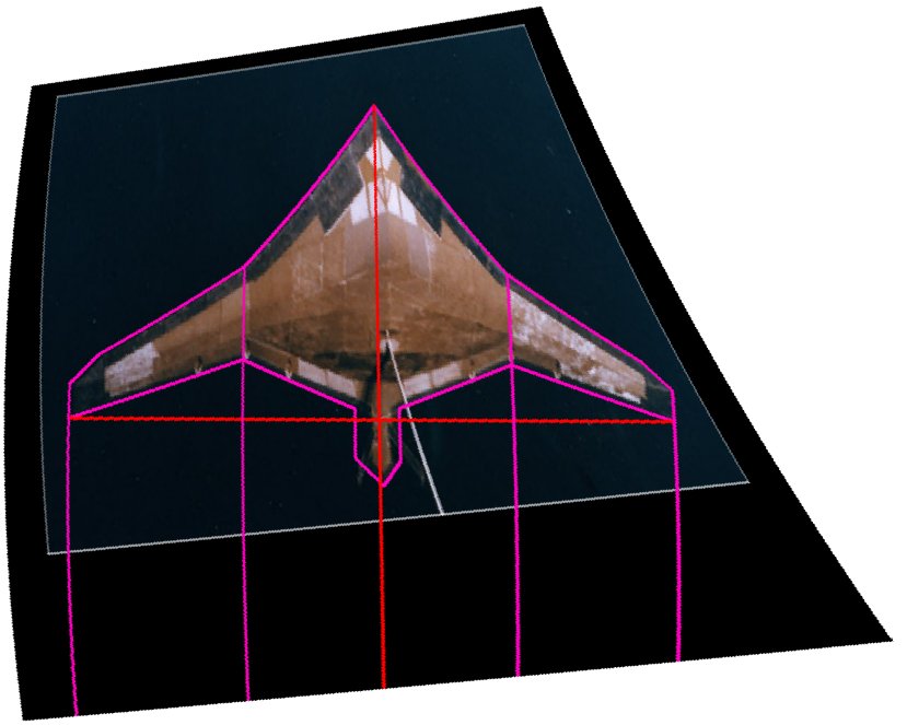
The changes are subtle, and probably not overly important at this scale, since things lines up fairly well right off the bat. This provides a new “baseline drawing” to work off of. Make sure that the CAD lines are clearly visible.
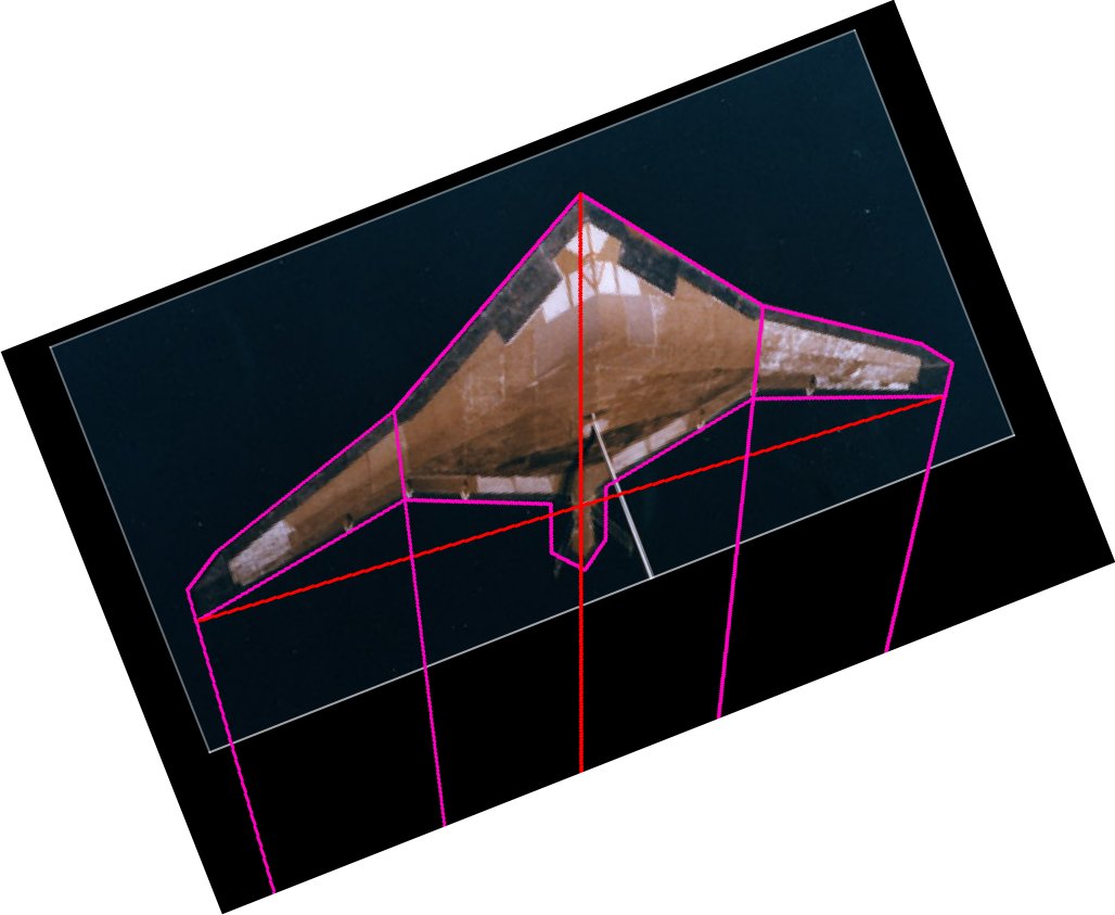
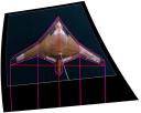
Rotate the image 21.5 degrees, so that the centerline is now vertical:
I use Paint Shop Pro… 1997 edition (hey, it works fine. Why upgrade what works?) . Found under “Effects” – “Geometric Effects” is “Skew.” use -17 vertical skew to get the trailing edge line to line up horizontally.
OK, we now have a photo of the vehicle lined up properly. However, the effects of perspective on the planform are visible, so they need to be dealt with. Fortunately, PSP has, under “Effects” – “Geometric Effects” a button for “Perspective – Vertical.” Throw in a “% Difference” of -47, and blammo, all of a sudden those perspective lines are now nearly parallel.
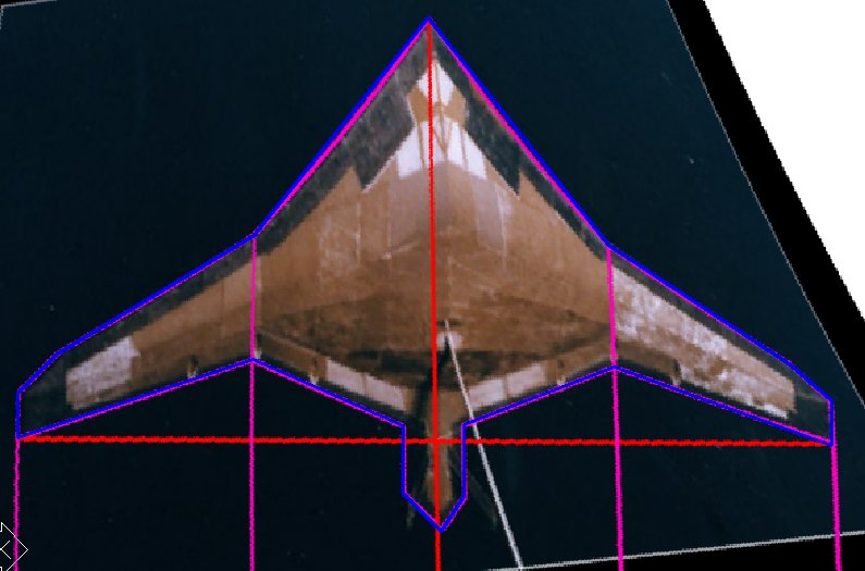
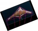
Take the resulting image, and paste it back into CAD and trace the outlines:
Hide the background image, then flip the right half of the lines over onto the left side:
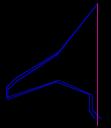
This shows some noticeable differences between the left and right halves of the reconstruction. Without knowing which is more accurate, again the thing to do is average. The easy way to do this is to again draw lines connecting related points:
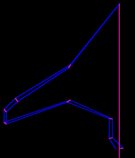
And then move the planform lines to the midpoints of the connecting lines:
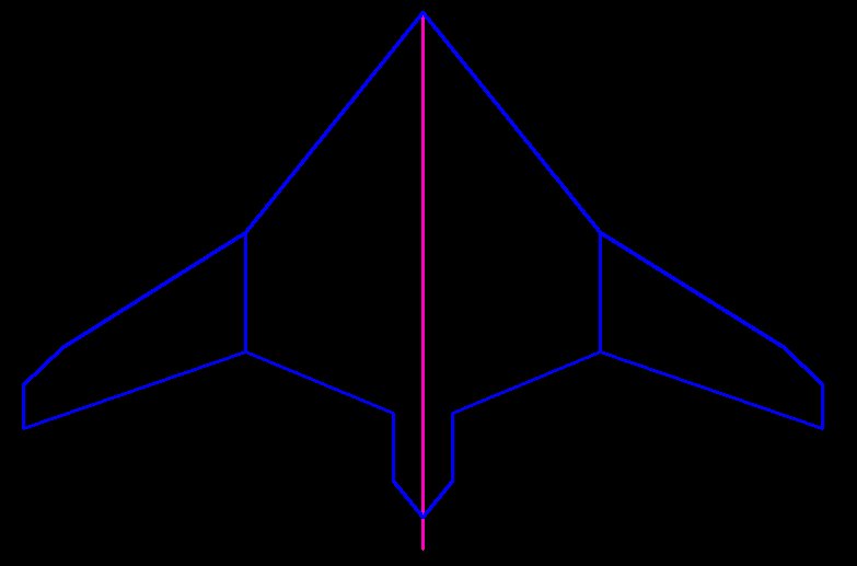
And then mirror the result:
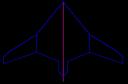
And there’s your planform!
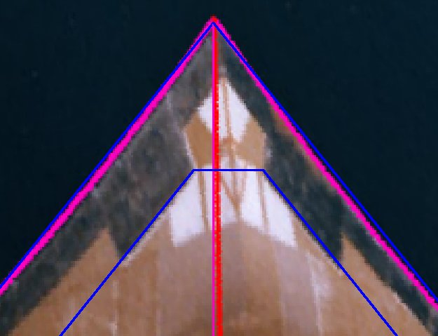
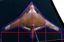
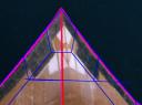
The surface details, such as the inlets, can be reconstructed in a similar fashion. Here the effort is aided by some of the basics of stealth… many lines are parallel. The “top” lines of the inlets are parallel to the leading edges. Exactly where the corners are can be determined by:
1) The vertical axis locations (Y-co-ordinates) are the same as on the photo.
2) The horizontal axis (X-axis) locations are less obvious. But fortunately the design is bilaterally symmetrical; thus the distance of the important points from the Y-axis will be the same for either side. Thus a line drawn on the photo from a left-side point to it’s related right-side point only need to be moved horizontally so that the midpoint of the connecting line is now on the Y-axis.

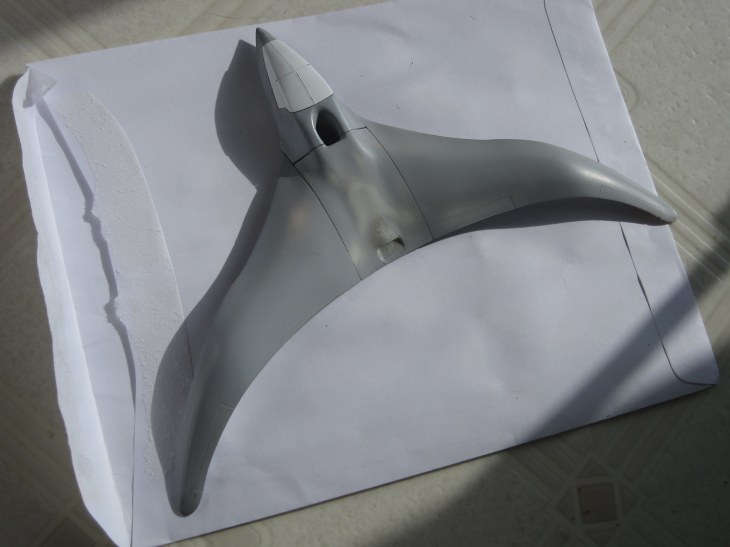
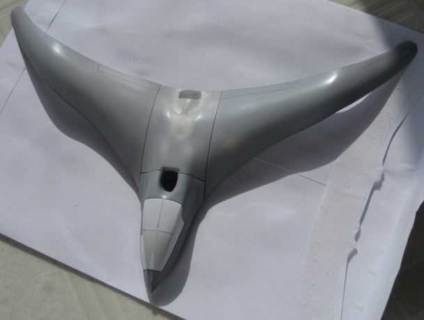
The other details can be worked out in similar fashions, thus providing a whole reconstruction (which I’ll probably post whenever the hell I get around to finishing it). With a design like this, the biggest problem would be in determining the underside contours… which, since the photo provides no details whatsoever, would be purest guesswork. In this case, though, a bit of B-2 and F-117 sculpting would seem appropriate.