Apr 012010
 

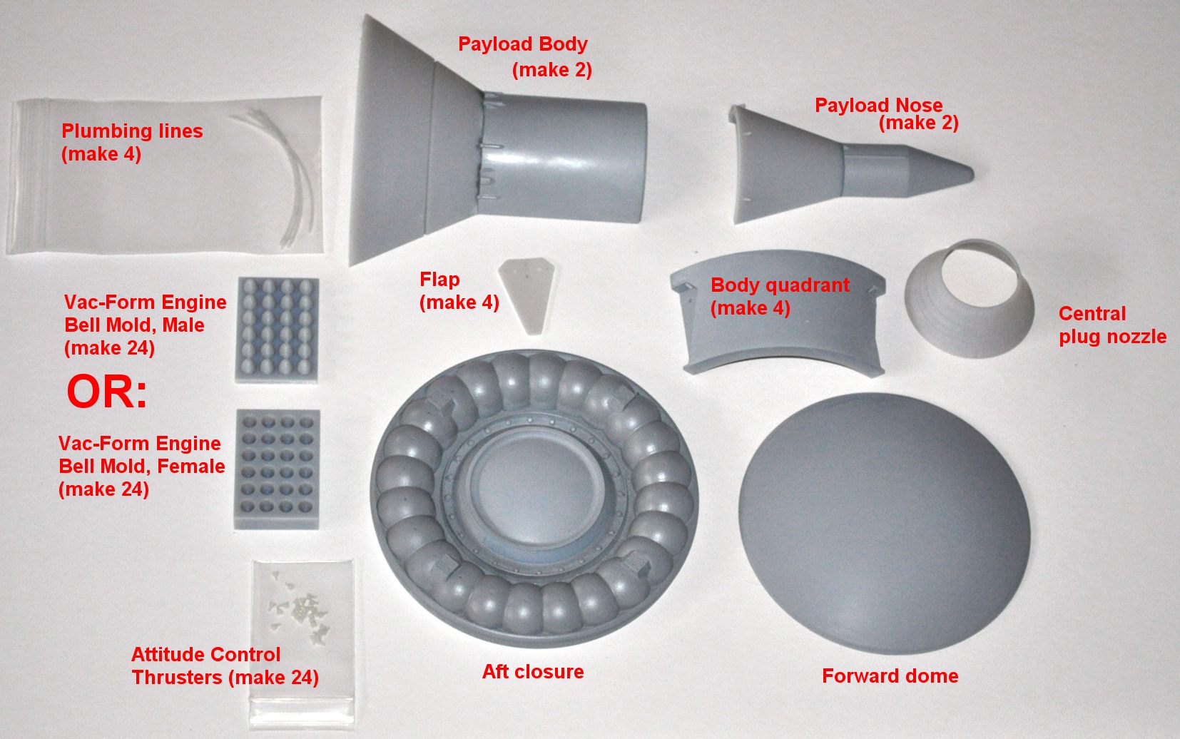
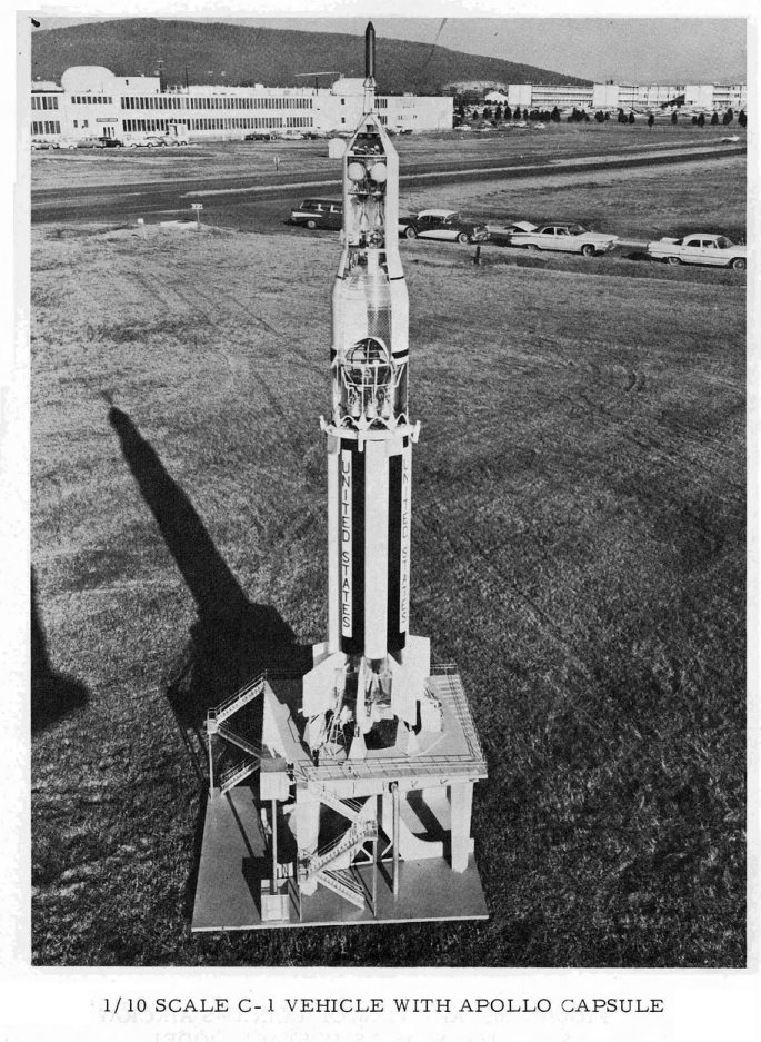
I recieved the 3-D “prints” of the Nexus model today. Holy crap… it’s huge! it’ll be an easy model, since the parts shoudl be relatively few… but it is truly hugenormous. Chances are now good that a line of 1/288 launchers will follow… Saturn Ib, Saturn V, others.

Also now in works is the CAD model for the 1/72 scale “Space: Above and Beyond” Hammerhead fighter. This one will be a hybrid of CAD/stereolithography and a lot of good old fashioned stratchbuilding. The CAD part will assure that the outlines are right and symetrical, the hand sculpting will get the contours far more efficiently than trying to hammer it out on the computer.

 Posted by at 11:12 pm
Mar 252010
 

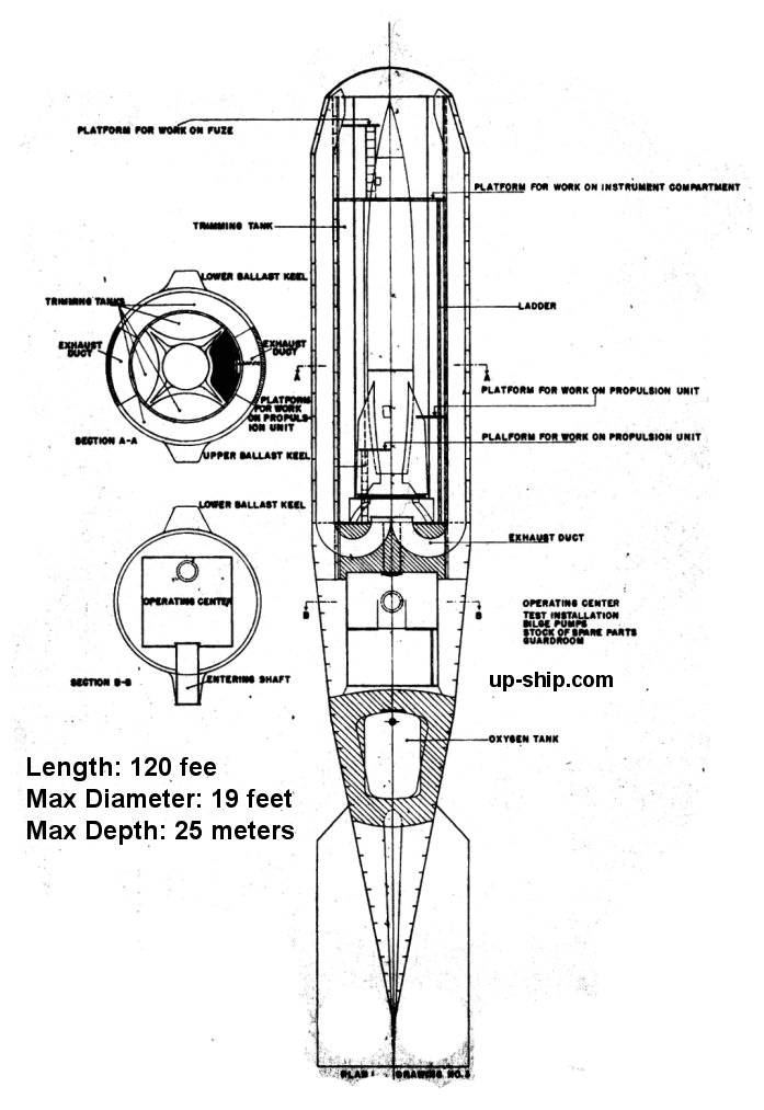
Numerous sources have mentioned “Prüfstand XII” (“Test Stand 12,” a code-name) and shown the same relatively unenlightening illustrations of it over the years. The idea behind it was this: at the same time production of the V-2 rocket was ramping up in wartime Germany, the western allies were overrunning V-2 launch bases. So the Germans had a missile, but nowhere to launch it from. The idea was raised about putting V-2’s in cannisters and towing them behind U-Boats; this resulted in the first serious design effort for a sea launched ballistic missile. The submarines available to the Germans at the time were far too small to permit carrying V-2s internally, and given the alcohol fuel and cryogenic liquid oxygen oxidizer, it would have been insanely unsafe to do so. So towed cannisters would allow the subs to transport V-2s in relative safety across the ocean.

The submarines would be stripped of armament; towing the cannisters they’d be essentially sitting ducks anyway. This would permit the installation of more powerful engines. A total of five cannisters could be towed at a time. They’d be towed in the horizontal attitude; once they arrived at the launching site, 500 or so miles from the supply base (indicating that the targets for the V-2 remain in Britain), crews would be transferred aboard and then… the subs would abandon them and return home. The cannisters raised to vertical. Before launch the noses of the cannisters would project above the water; bow doors would open. The V-2s would be launched from them much like any other silo-launched missile, with ducts along the sides to the silo to carry the exhaust away from the fragile missile. The cannister would button up again and resubmerge. Four or five days later the sub would return with another five cannisters and would pick up the first five for return and refurb.

A great deal of the plan seems to have been incredibly optimistic, of course.

I recently stumbled across a post-war writeup of the concept by several of the Germans who worked on it. Included were a number of remarkable drawings and diagrams, finally showing the thing in good detail. The same basic concept was pitched to the US Navy in 1955 for use with Jupiter IRBMs, with no success.

I’ve numerous more diagrams of this. I think it’d make a good APR article… and it’d make a spiffy cutaway display model. If anyone would be interested in contracting me to build them such a model… just let me know.

prufstand-xii.jpg

 Posted by at 1:03 pm
Feb 282010
 

Now that the X-37 is back in the news, here are some photos of a large display model of it. These shots were taken at Marshall Space Flight Center back in 2005.

Wow. Five years ago. The pace of aerospace development is just blistering.

pdr_0101.jpg  pdr_0102.jpg  pdr_0103.jpg

And here are three pics of a similar model on display at the Hunstville airport, from the same expedition.

pdr_0187.jpg   pdr_0188.jpg  pdr_0189.jpg

 Posted by at 7:40 pm
Feb 262010
 

A followup to this. A visit to the local thrift-dump scored three crappy old cookers. Of the three, one had a cord that fit the vac former (and another one that might, after a visit with Mr. Dremel Tool). With some trepidation, it was installed, plugged in and turned on. While it smelled of burning shoggoths, the heating element *did* warm to a nice hot orange glow, the 15-year-old sheet of plastic sagged as badly as my hopes and dreams, and the shopvac provided adequate suction to make passable copies of the two empty cans of cat food that happened to be near at hand. Woo! The power cord itself got disturbingly warm, however.
So, now I will be able to make some vac-formed items. The long-dreamed-of, long despised for being incredibly expensive 1/288 scale “Archangel Michael” seems like a possible prospect.

 Posted by at 9:44 pm
Feb 222010
 

Sometime around 1994 I bought a vacuum-forming machine, the “Hobby Vac System 2.” It worked well, but as time went by my need for it faded, and it got stuffed out of sight. Recently I decided to haul it out of mothballs, as I’ve a few projects that would benefit from vacuum forming. It’s dusty as hell, but seems to be in good shape. But there’s one problem: the power cord. I can’t find the damn thing. Last time I can defintely recall seeing it was a dozen years and two moves ago.

So I packed it up and took it to the local electrician/appliance store, to see what they can tell me… which was “not much” and “good luck.” A search for “Hobby Vac System 2” turns up precisely zip. The plug seems to be a standard sort of appliance plug, perhaps from some sort of grill or cooker or something. It had, as memory serves, a single long central prong, plus the two side sockets as would fit the socket in the photos below. Does this look familiar to anyone? Anyone know where I might be able to procure a replacement?

dsc_3202.jpg  dsc_3203.jpg  dsc_3204.jpg  dsc_3205.jpg

 Posted by at 2:30 pm
Feb 012010
 

Photos (courtesy Dennis R. Jenkins) showing a few models of the Shuttle orbiter circa 1973, just before the final configuration was settled upon. Notable differences include hiding the forward RCS jets behind doors and extending the fairing for the OMS pods forward onto the cargo bay doors (presumably an aerodynamics consideration). The moldline in the area of the cockpit also looks a bit different.

The boosters and the external tank are much more different, however. This is presumably due to the model being made by Rockwell, while the boosters were still effectively as-yet undesigned – and unwon – by Thiokol. The external tank certainly looks pretty narrow. The C-5 Shuttle Carrier Aircraft model was probably built by or for Lockheed.
shuttle-model-05.jpg

shuttle-model-09.jpg

shuttle-model-10.jpg

shuttle-sca-concepts-03.jpg

 Posted by at 11:52 pm
Jan 212010
 

The landing boats depicted in the new 1/288 scale Orion “Battleship” model are not pure invention on my part. But sadly, neither are they reconstructed from clear blueprints. They are the result of some deduction and detection and educated reconstruction.

First off, they were described to me by one of the actual Orion engineers as being about the size of a PT boat, and seating about 20. Additionally, they were “diamond shaped,” and used an extended skid during re-entry. The diamond shape part was a bit of a head scratcher, as I could not get further clarification on exactly what that meant (there were some communication difficulties). So, I looked through the open literature from the late 50’s/very early 60’s to see if I could find something from the NACA, USAF or Convair/General Dynamics that would fit the bill. I found a few, starting with this one:

rv1.gif

And another from the NACA that looked more promising:

rv2.gif

I went with the latter design as the basis for the landing boat for the CAD model of the Battleship that I put together for issue V2N2 of Aerospace Projects Review (go here and buy a copy, ya mooches).

covertest2a.jpg

orionbattleship2d-model.jpg

As for the re-entry shielding skid, that was confusing until I was directed to this snippet from the December 1960 issue of Flying Review:

skid-flyingreviewdec1960.jpg

Not much I could really do with that, though.

As so often happens, once the product is out the door, more information comes in. In this case, I was put in contact with one of the artists employed by General Atomic Back In The Day (see HERE for more discussion of the long-lost Time Of Quality Aerospace Artwork), and it happens that he illustrated the landing boat. Sadly, the art seems to have been stuffed down the memory hole… but a single photo of his desk at the time remains, and on his desk was a painting of the landing boat:

orion-art.JPG

No better resolution of that photo is available. The landing boat is on the far right. The other two paintings supposedly illustrate some other aspects of the Orion program, but there’s not enough visible to make heads or tails of ’em other than they seem to be in Earth orbit. An enlargement of the landing boat:

orion-art2.jpg

This clearly shows a head-on view of the boat. This verifies the “diamond shape,” at least as far as the cross-section of the craft. Also visible is a raised canopy, discrete wings, tricycle landing gear and a braking chute. As it turns out, the first NACA re-entry shape I’d looked at and passed over was closer to the correct shape.

Something about the wings bothered me. At last I recalled that I had seen something very like them before… in a Convair Astronautics Division Project Apollo proposal from 1961. Keep in mind, at the time General Atomic, like Convair, was a division of General Dynamics… and the two divisions were separated by only a few miles. It’s thus quite likely that re-entry vehicle design work at Convair was fed to General Atomic. Here, an advanced Apollo system was briefly discussed that would use a lifting body for the command module, a lifting body with stowed wings that seem to be the spitting image of those shown on the landing boat painting.

gd-apollo-m-3-config.jpg

And so I took the “diamond shaped” front view, the NACA RV work, and the 1961 Apollo wings, and built from them a Landing Boat.

orionmodel11art.jpg

orionmodel11art1.jpg

orionmodel11art2.jpg

orionmodel11art3.jpg

orionmodel11art4.jpg

boats.jpg

orionmodel9a.jpg

Ta-Da…

 Posted by at 8:08 pm
Jan 182010
 

Fantastic Plastic has (or is just about to) released the 1/288 scale model of the Orion “Battleship” that I mastered for ’em. Check it out:

http://fantastic-plastic.com/ProjectOrionBattleshipPage.htm

orionbattleshipboxart-600.jpg

projectorion-main.jpg

There are just a whole hell of a lot of parts in this kit:

projectorionbattleship-what.jpg

Included in the kit are three complete weapons bays and one complete “boat” bay (the ship would have three, but it was decided to just kit one). The black “darts” are the actual landing boats, used to transports crews to and from the surface; the red cylinders are the “taxis” used to transport crew from spacecraft to spacecraft. The weapons bays each include one 5-inch naval gun turret and two hypothetical “Casaba Howitzer”  weapons systems.

projectorion-landingboats.jpg

You can read more about the design – as well as see further renderings and inboard/exterior diagrams in issue V2N2 of Aerospace Projects Review.

Some previous blog posts about this model project:

http://up-ship.com/blog/blog/?p=4231

 http://up-ship.com/blog/blog/?p=4024

 http://up-ship.com/blog/blog/?p=3237

http://up-ship.com/blog/blog/?p=3216

 Posted by at 10:37 pm
Jan 132010
 

Space Drawing Set 21 contains a large format (13378X5402 pixels) full-color scan of a cyanotype blueprint of the Minuteman 1 ICBM. The diagram is for a display model, but presents full-scale dimensions as well as considerable external detail … thus perfect for modelmakers. Boeing drawing 25-27135, dated May, 1961. Good, clear diagrams of the Minuteman are hard to find… this is by far the best I’ve ever seen in the unclassified world.

The ZIPped file contains the large format color scan, a grayscale version at that size, and half-sized versions for easier viewing and printing. NOTE: the filenames are actually “Halfsize” and “Quartersize,” becuase the true original full-rez scan is a prohibitively large file (over 140 meg). If this smaller set sells, the fullsize version might be made available as a CD-only item.

Space Drawing Set 21 can be purchased for download for $5.50.

..

sdwg21ad.jpg

 Posted by at 10:23 am