Some early views of the 1/72 SLAM missile model. The TORY reactor will be a separate part, visible from the front through the inlet and from the rear through the nozzle.
Official: the next model that I will master for Fantastic Plastic is the Project Pluto nuclear ramjet cruise missile. The next model was *supposed* to be the “2001” Space Station V, but I’m separated from my references for that. But the Pluto stuff I have on hand.
Currently undetermined is the scale. 1/72 is the obvious choice, but 1/48 might be possible as well. Some measure of “cutaway model” will be inevitable, due to the wide open nature of the inlet and nozzle; a full cutaway with all the innards is unlikely, but possible at larger scales. If you have a preference, leave a comment.
The parts for the 1/72 Hammerhead were shipped out just before I left Utah. Here’s a photo of them.
Low-speed “free flight” tunnel tests of the HYWARDS hypersonic boost glider, conducted at NASA-Langley in 1959. The HYWARDS was an outgrowth – sorta – of the BoMi and X-15 programs. More on it can be seen in APR issue V2N4, in both the BoMi Part 3 and Ames Mach 10 articles.
[youtube 1j0q5aKb45g]
The HYWARDS vehicle was a nicely angular design. Looks great, seemed to fly ok at low speed, but would have had nightmarish heating issues along those leading edges. The cones on the wingtips were control surfaces.
Note in the video that there appears to be a second, fixed model being tested at the same time. The second model appears to have wings of variable incidence, changing from test to test.
After yesterdays XB-53 free flight tunnel test model post, I looked a little into how a “free flight” wind tunnel is done. The 12-foot Low Speed Tunnel at NASA-Langley (and before at NACA-Langley… built in 1938) turns out to be a remarkably clever structure, and a love-lived one. The tunnel section itself is relatively short and stubby, and is mounted on a pivot that allows it to pitch up and down. In order to have a proper tunnel air recirculation system, the short length of tunnel is mounted at the center of a sphere. The result is that no matter how the test section is tilted, the flow path for the air recirculatiuon remains identical… without having to actually move the whole structure.
By tilting the test section, the test engineers can turn the downward force of gravity into, essentially, a partially forward force of thrust. There’s no such thing as an object that will hover without either bouyancy (like a balloon) or lift generated by either aerodynamic forces or thrust from lift-jets or the like. So a model airplane, in order to fly, needs to have lift. Placed in a wind tunnel, that lift is generated by air flowing over the wings. But if the wind tunnel is horizontal and the model is not constrained in some way (like a kite), then the wind will pick it up, to be sure, but will also blow it backwards. As the model is blown along, it will of course lose speed with respect to the wind, and thus lose lift and drop back down. But if the wind tunnel is inclined at the right angle, then the model will be in a constant state of trying to glide forward and downward… and if its downward glide angle is the same as the angle of the tunnel… it’ll hover. You just need to tinker with the angle to get it right.
Exterior photo:
Cutaway art:
And here’s a YouTube video (embedding probably disabled, but click on through to it) that shows a scale cutaway model of the structure. Presumably at one point there was, or was supposed to be, audio, but it’s silent. There are several minutes of static shots, but eventually it does get around to showing how the test section pitches up and down. I especially liked the very last scene… apparently in 1939 engineers not only had to wear suits every damned day at pretty much all times no matter what silly-assed thing they were doing (like flying a tiny toy airplane witha stick), but hats, too.
[youtube ousrJAj4itw]
Me, I’d think that today it might be easier and cheaper to just actually *fly* the models than to build this rather sizable structure. But that is due in no small part to the fact that today we have dirt-cheap, lightweight radio control systems. Without such systems, a tunnel like this would seem to be a pretty spiffy way to get long-duration test data for flying scale models.
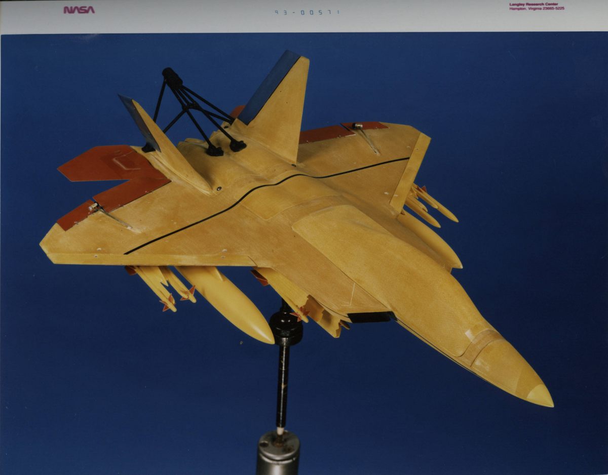
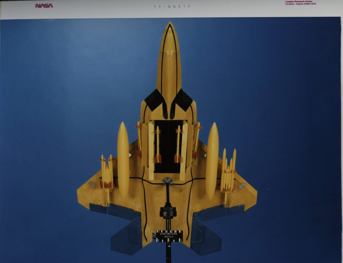
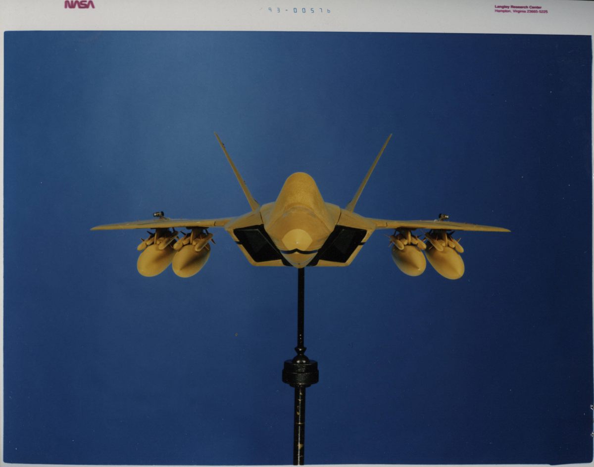
NASA photos of a large model of the F-22 with some differences… a two-seat canopy and a whole lot of stuff hanging under the wings. This does not appear to be a standard wind tunnel model… it appears to be made of thin Kevlar-fiber/epoxy sheets. This would indicate that the model was meant to fly… whether dropped from a helicopter or other aircraft, or “flown” in a wind tunnel, I haven’t the data to say. The latter seems likely. Note that the control surfaces are hinged and appear to have actuators. Circa 1993.
1) Currently in active work: finishing the 1/144 and 1/72 “Hammerhead” models for Fantastic Plastic. These were “printed” via stereolithography… this results in all the accuracy and symmetry to could possibly want, but it also means a really rough surface finish that takes a *lot* of work to clean up.
2) Next on the schedule is physical finishing of the printed “X-15D” parts. This should be pretty easy compared to the Hammerheads, due to simpler geometry.
3) CAD modelling of new nose and aft-fuselage air inlets for a 1/144 conversion kit… converting the Hasegawa B-36 into the nuclear reactor-equipped NB-36H test aircraft. This is to be done for another “garage kit” company. An X-6 *may* follow that.
4,5,6) Competition among CAD modeling of Space Station 5, a large-scale X-15 project and an X-42 desktop display model, with physical finishing of 1/144 “Dragon” parts thrown in there somewhere as well..
Around about ten years ago (during another employment dry spell), I got a contract from NASA-MSFC to build a few models of the General Atomic 10-meter Orion. I built five, I believe… three in 1/144 scale, two in 1/72. I took some fairly horrible photos of them before shipping them off. These were of course film photos, a digital camera still being another three or so years in my future. Two of the 1/144 models are shown below:
I could certainly do far better today. A combination of vastly better references and improved modelling skills could produce one hell of an Orion.


