The December 2022 rewards are available for APR Patrons and Subscribers. This latest package includes:
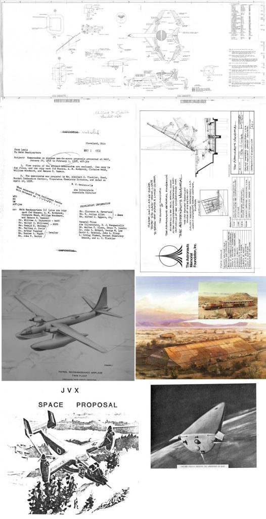
Large Format Diagram: AWACS model diagram
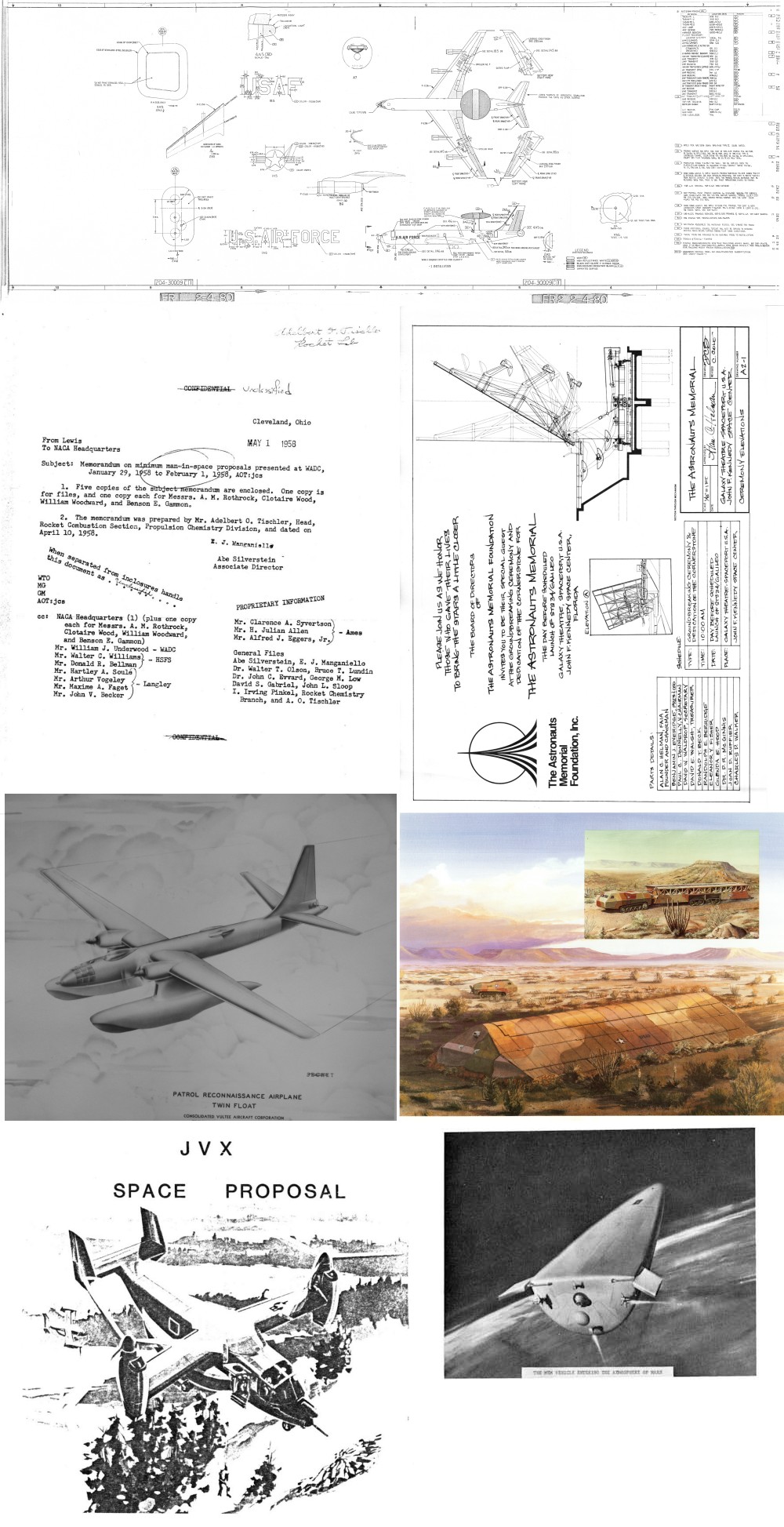
Document: “Preliminary Design of a Mars Excursion Module,” 1964 conference paper, Philco
Document: “Astronauts Memorial” 2 diagrams
Document: “Patrol Reconnaissance Airplane Twin Float,” Convair brochure (via photos), 1944. Two piston engines, two turbojets
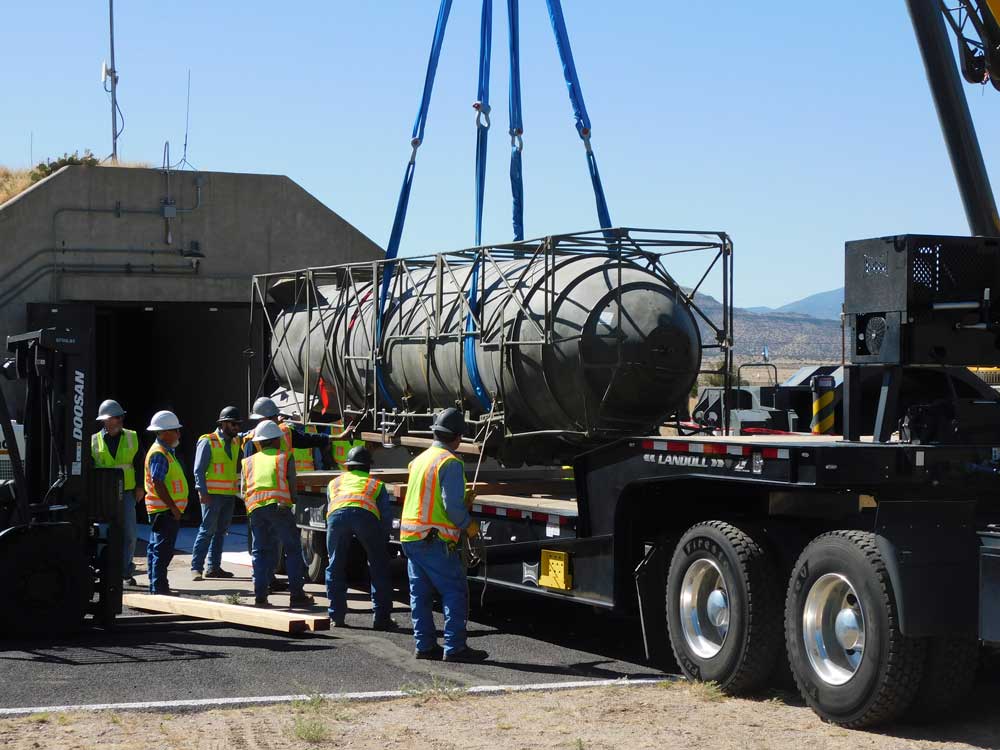
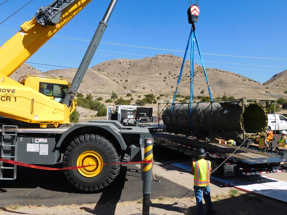
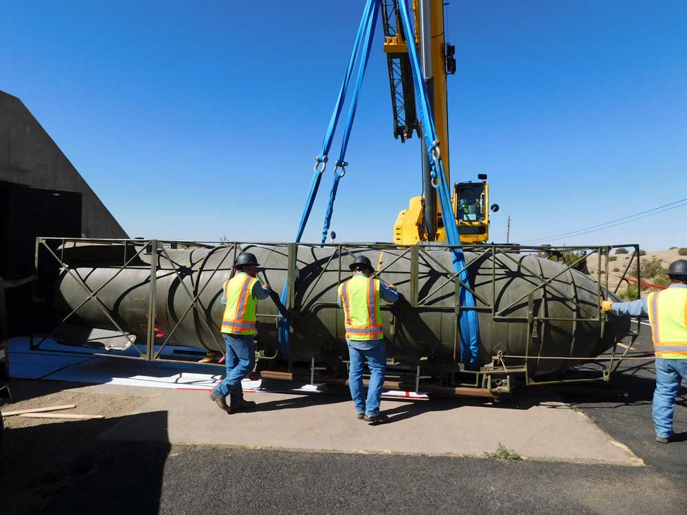
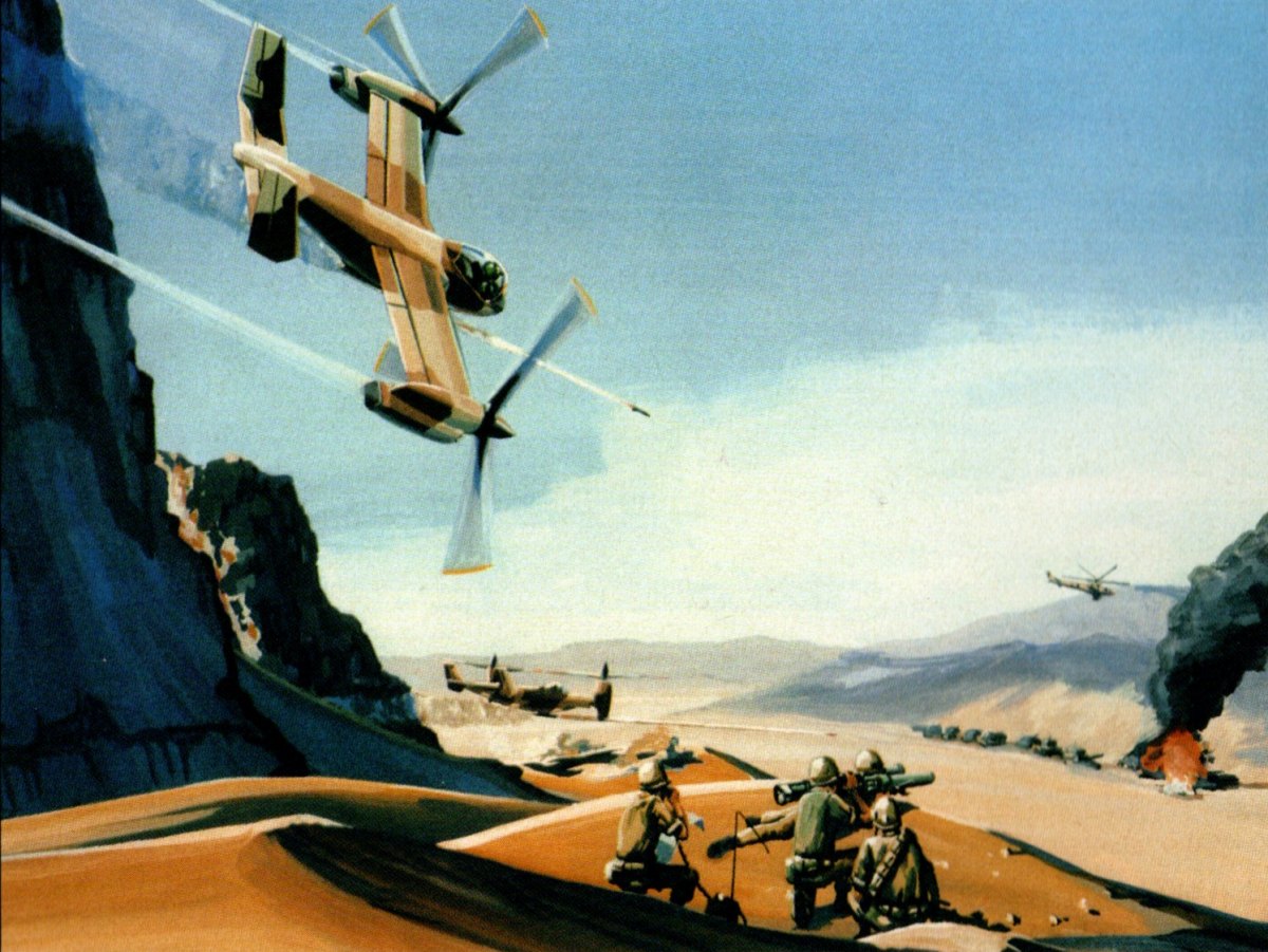
Document: “Hard Mobile Launcher,” Martin Marietta PR, two images. One photo, one artists impression
Document: “JVX Space Proposal” apparently a fragment, 1984 Bell maps of manufacturing facilities for what would become the V-22
Document: “Minimum Man In Space,” 1958 NACA memo describing proposals made to Wright Air Development Center for what would become the Mercury program
If you would like to help fund the acquisition and preservation of such things, along with getting high quality scans for yourself, please consider signing on either for the APR Patreon or the APR Monthly Historical Documents Program. Back issues are available for purchase by patrons and subscribers.
And because I forgot to post about it at the time, the November 2022 rewards were made available a month ago:
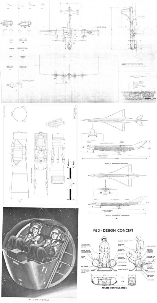
Large Format Diagram: B-50A Superfortress Model Diagram
Document: “Design Study of a One Man Lunar Transportation device,” 1964 North American Aviation conference paper on a rocket “hopper”
Document: “Project EGRESS (Emergency Global Rescue, Escape and Survival System),” 1964 Martin conference paper on ejection capsule for aerospacecraft
Document: “The Hydrogen Fueled Hypersonic Transport,” 1968 Convair conference paper
CAD Diagram: Mach 3 turbojets: Allison 700 B-2 (J89), GE YJ-93-GE-3 (cutaway), P&W J58
If you would like to help fund the acquisition and preservation of such things, along with getting high quality scans for yourself, please consider signing on either for the APR Patreon or the APR Monthly Historical Documents Program. Back issues are available for purchase by patrons and subscribers.