Sikorsky is currently flying the S-97 “Raider” helicopter featuring the ABC (Advancing Blade Concept) rotor. ABC rotors look like conventional coaxial rotors, but differ in being structurally stiff and inflexible. The idea is that ABC rotors allow faster flight: in a conventional single-rotor helicopter, the faster airflow means that on one side of the rotor disk, the “advancing blade” slams into the air at a very high speed, potentially generating a lot of lift. But on the other side of the disk, the “trailing rotor,” which is moving aft at a speed not far off from the airflow, generates very little lift. This of course imbalances the aircraft and limits forward speed. The ABC system, by having coaxial rotors, make sure that there is always balanced lift. The S-97 is not the first helicopter that Sikorsky has built with ABC rotors; the S-69 flew in the 1970s, reaching a top speed of 260 knots. But it suffered from serious vibration issues and did not lead to a production aircraft. The S-97 seems to have fixed most of the issues, and it is hoped that a production contract may eventually come.
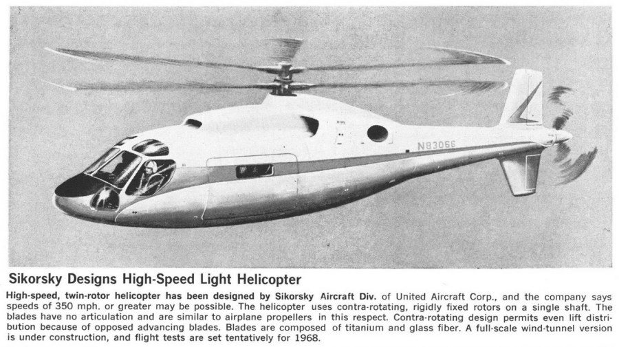
The ABC concept dates back *at* *least* 52 years. Below is an illustration from 1966. Interestingly this design more closely resembles – at least superficially – the S-97 than the S-67. The S-69 used two turbofan engines to provide forward thrust, while the S-97 used, like this illustration, a pusher propeller.