To continue…
A uranium plasma with a core temperature of 42,000 degrees Rankine (23,333 K) is simply incapable of being held by any solid structure. The highest melting point of any known substance is tantalum hafnium carbide, at 4488 K. The uranium plasma would simply evaporate any material it came into contact with.
So, the trick was to make sure the uranium plasma didn’t come into contact with any solid materials. To do this, a “radial inflow vortex” was to be employed. Within the cylindrical reactor chambers, the uranium plasma would be held within the center, away from direct contact with the walls, by a rapidly rotating sheath of neon gas. Injected tangentially along the walls, the neon gas would travel in a helical pattern up the length of the cylinder and would be extracted at the forward end, to be cooled and recycled back into the system. The rapid rotation of the neon gas would be translated to the uranium plasma, and the whole plug of gas would spin at a high rate. Centrifugal force would keep the system properly distributed… while normally it would seem that a uranium gas would be denser than neon, the fact was that at the fabulously high temperatures involved, the uranium would be lower density than the cooler neon, and thus would be suspended in the core, away from the walls.
While the core temperature of the uranium plasma was 42,000 R, the outer surface would be a comparatively chilly 15,000 R. This is of course still far in excess of what any material structure can handle. But the neon, already a gas, could handle 15,000 R; due to the vortex structure, the innermost surface of the neon layer, where it was in contact with the uranium, would also be at 15,000 R, but a steep temperature gradient dropped the temperature to a modest, and structurally possible, temperature of 2000 R at the walls. The thickness of the neon gas layer was estimated to be under 0.05 feet.
Each of the seven chambers would have a neon flow rate of 2.96 pounds per second, and an axial velocity of 1.95 feet per second and a tangential velocity of 10 feet per second, with a total dwell time of 3.8 seconds. The hot neon would extract energy from the reactor, of course, to the sum of 4,120 BTU/sec. The hot neon would be used, in part, to pre-warm the hydrogen fuel.
—————–
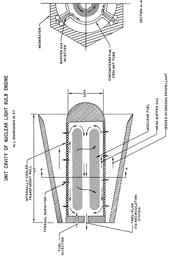
Schematic view of one of the seven chambers in the nuclear lightbulb engine (United Aircraft)
————–
Even with the neon buffer layer, a simple glass wall would not be sufficient to withstand the harsh environment. As well as simply being in contact with 2000 R neon gas, the transparent wall would also have a vast sleet of radiation passing through it… infra-red, gamma rays, neutrons, the whole spectrum. Once again there was the problem that no transparent material would possibly be able to survive the environment. Even the most optically transparent material will absorb some of the radiation passing through it… and this absorbed energy will be converted directly to heat. It would not take very long at all for the clearest substance to get incredibly hot… which, of course, was the goal with the hydrogen propellant. What was desired for the propellant was manifestly not desired for the structure.
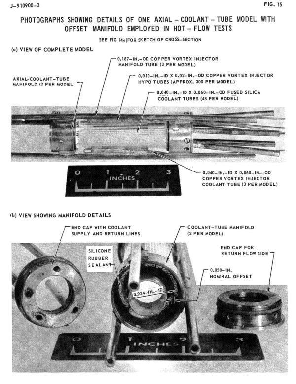
So the transparent walls were to be made not out of monolithic sheets, but thin-walled tubes. High-purity fused silica was the baselined material of choice. Thought was given to single-crystal beryllium oxide and synthetic quartz as materials, as they had better transparency in the ultraviolet, but production of the required tubes using these materials was undemonstrated. To cool the tubes, hydrogen gas would be pumped through.
The cylindrical walls were built in three 120-degree radial segments. At the end of each segment was a manifold for injection or extraction of the hydrogen coolant, so the hydrogen did not travel very far around the circumference of the cylinder. This assured that the hydrogen did not have time to heat up to much, and that the silica glass would be maintained at a reasonably constant temperature of between 800 and 1100 Celcius (yes, the reports have units all over the place). Corning Type 7940 and General Electric Type 151 fused silicas typically had a purity of SiO2 of 99.997 percent, with Al2O3 being the primary impurity. Purity was essential… the greater the purity, the greater the transparency.
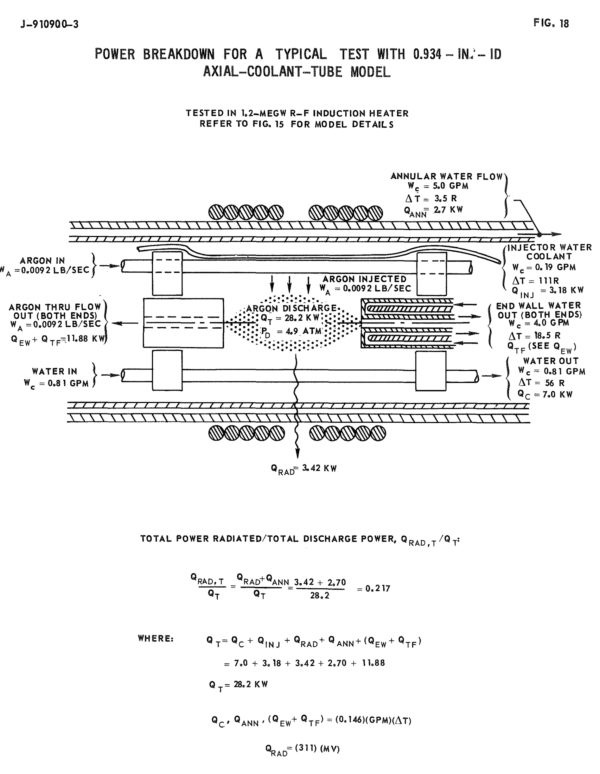
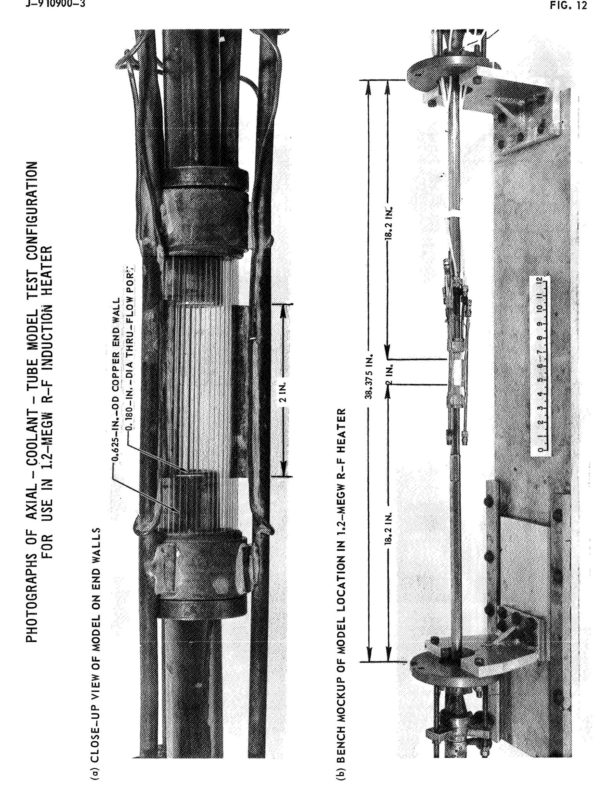
Since this was the late 1960’s, United Aircraft actually ran a number of physical experiments to demonstrate the feasibility of their designs and materials, rather than a series of colorful computer simulations. As operating a uranium plasma reaction was somewhat beyond the scope and funding of their contract with NASA, they instead used a 1.2 megawatt RF induction heater to generate an argon plasma of about 15,000 R in a subscale “reactor.” The subscale test setup used both axial tubes (with wall thicknesses down to 0.005inches) and circumferential tubes potted into the manifold with RTV silicone.
———–
Schematic view of test setup (United Aircraft)
————–
Test setup with annular tubing (United Aircraft)
————
Details of test hardware (United Aircraft)
——————–
In the tests, water rather than hydrogen was used as the coolant.
Test results were generally encouraging, but a number of issues were discovered. One of the more odd things that was noted in this and other testing was that the color of the glass tubes was a variable during the course of nuclear engine operation. Radiation damage to the glass would cause the glass to gradually become blue, then purple, then black. This is, of course, fatal to not only the functioning of the engine, but the survivability of the glass. Any amount of coloring would cause massive increase in radiation absorption, resulting in rapid overheating and structural failure. But over 800 Celsius, the glass would thermally anneal… which would wipe out the coloration and restore transparency. Thus the need to keep the glass operating at a minimum of 800 C. But above 1100 C, devitrification of the glass would occur… it would continue to be perfectly serviceable clear glass, but once it began to cool down after engine shutdown the surface of the glass would turn milky white due to a myriad of microscopic surface cracks. This would cause the glass to overheat if the engine was restarted. And thus the need to make sure that the glass did not rise above 1100 C.
————–
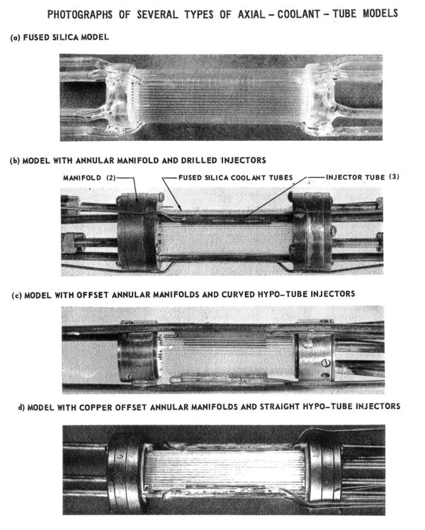
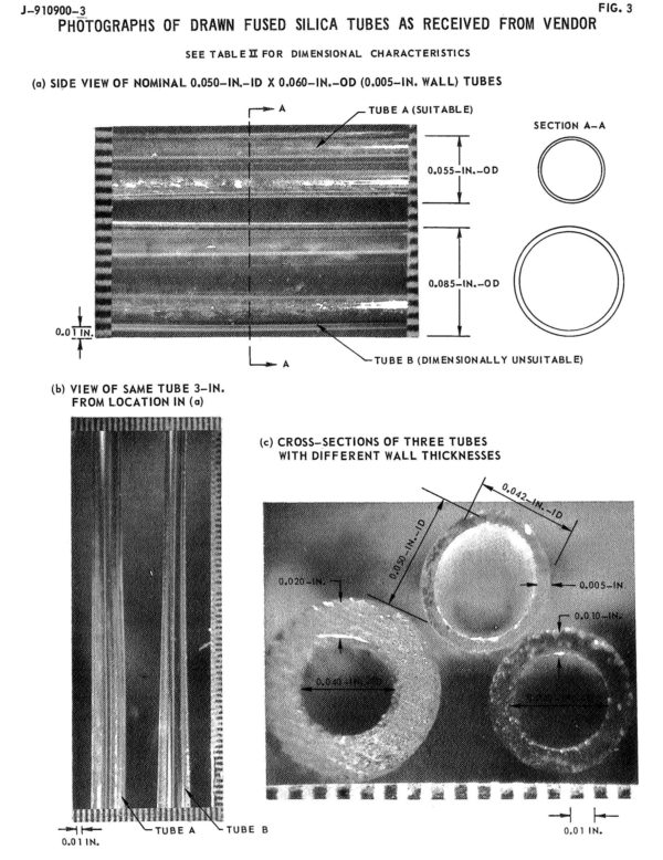
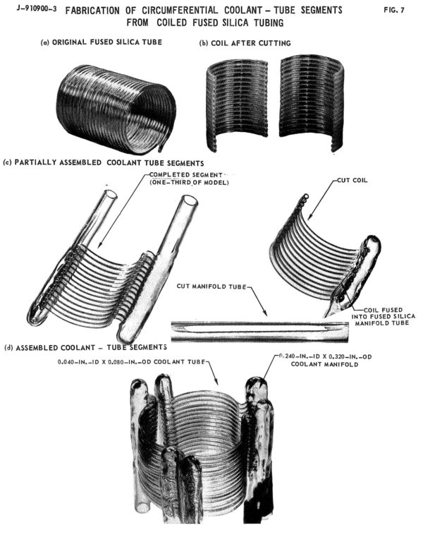
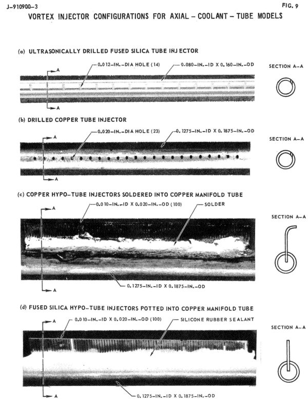

Photos of test hardware (United Aircraft)
______________
To Be Continued…
16 Responses to “Nuclear Lightbulb, Part 3”
Sorry, the comment form is closed at this time.
Did the design have enough T/W to be used on a launch vehicle? Because GOD DAMN THIS IS AWESOME.
Look up “Liberty Ship.” My understanding was that that was a very large heavy lift booster concept using this engine design.
They actually demonstrated a transparent wall that worked at those temperatures? This is actually starting to sound possible – I can’t to hear more!
Forget the Moon! I might watch this from Mars!
Jim
Lordy….I think I would rather use ol’bang-bang Orion. Lot less complicated!
So convection is basically the trump card against all heat. Amazing how they found a solution, although engineering a full scale model would be beastly.
Talk about a fragile technology…either it’s all going to work exactly right, or it’s to go spectacularly wrong if any part of it goes even slightly off-kilter.
“tps” is right; this makes Orion look simple and reliable by comparison.
This thing is like using the Hindenburg as a mounting for a giant flying flamethrower. 😀
I’m sure the whole thing could be made to work right for several seconds at a time with enough effort. 😉
You can tell this whole concept goes way back before the full understanding of the part chaos theory plays in turbulent gas motion.
I’ll say one thing for it though; it took some real imagination on the part of the engineers to be able to come up with a concept this involved, practical or not.
In an earlier age, these guys would not only have the four elephants riding on the back of the turtle part figured out, but what exactly the turtle was walking on and why it was going around in year-long circles.
> Did the design have enough T/W to be used on a launch vehicle?
It did not. That did not stop them from proposing just that, though…
>It did not. That did not stop them from proposing just that, though…
Oh god. Please…share…
It’s coming. Might wind up being in “Nuclear Lightbulb, Part Bagrillion,” but it’s coming.
Wildly optimistic proposal for a nuclear lightbulb launch vehicle
http://www.projectrho.com/rocket/rocket3ay.html#libertyship
@Winchell I recall reading somewhere that the engines might frack up each other with their neutron emissions.
Or something. It was a few years back.
Clayton wrote:
“Winchell I recall reading somewhere that the engines might frack up each other with their neutron emissions.”
That’s a good point – with a single engine it wouldn’t be a problem, but as soon as you cluster them, it’s going to take a lot of shielding to prevent neutron emissions from one from affecting the engines in its vicinity.
The same argument applies to all nuclear fission engines; in NERVA you had your nuclear radiation shield between the engine and crew section of the spacecraft, but how about other engines mounted side-by-side in a clustered arrangement? That weight could really cut into the overall advantage of the concept.
These design descriptions NEED to be in high school physics textbooks. Scott and Winchell should write one. Or accept the mantle from Jearl Walker and redo the next version of Halliday and Resnick with hard core retro nuclear rocket examples.
I wish I could help.
@Pat the multiple NTR designs I’ve seen didn’t seem to have any kind of shielding from each other.
Maybe it a matter of intensity? :S